Table of Contents
Advertisement
Quick Links
Advertisement
Table of Contents

Related Manuals for NSD ABSOCODER VE-2PR Series


Summary of Contents for NSD ABSOCODER VE-2PR Series
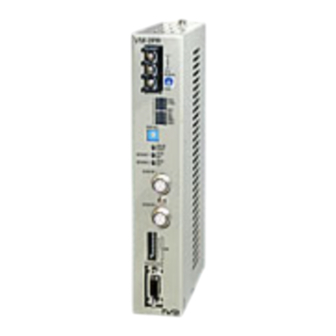
- Page 1 ZEF004381004 Specifications & Instruction Manual ABSOCODER Converter For PROFIBUS-DP VE-2PR-□ STYLE1 VM-2PR STYLE1 VE-2PR-□ STYLE1 □model Applicable sensor _: VRE-P028/062 VRE-16TS062 VM-2PR STYLE1 Applicable sensor MRE-32SP062 MRE-G□SP062...
-
Page 3: General Safety Rules
- Be sure to store the controller in designed temperature and humidity CAUTION range, and do not exposed to direct sunlight. - Be sure to consult with NSD when the controller is stored for long - Be sure to handle the controller as industrial waste while periods. - Page 4 <VE-2PR-□/VM-2PR STYLE1 Specifications & Instruction Manual Revision History> ※ The Document No. appears at the upper right of this manual's cover page. Document No. Date Revision Description ZEF004381000 11.August,2004 1st Edition Japanese document: ZEF004380901 ZEF004381001 12.September,2008 2nd Edition Japanese document: ZEF004380902 3rd Edition ZEF004381002 11.July.,2011...
-
Page 5: Table Of Contents
CONTENTS 1. Converter Overview ..................1 1-1. Overview ..............................1 1-2. Features ..............................2 1-3. System configuration ..........................3 2. Specifications ....................4 2-1. ABSOCODER Converter Specifications ....................4 2-2. ABSOCODER sensor & extension sensor cable specifications ............6 3. Dimensions ..................... 9 3-1. -
Page 6: Converter Overview
1. Converter Overview 1-1. Overview This manual describes the specifications and instruction procedures for the VE-2PR/VM-2PR STYLE1 which is used together with PROFIBUS-DP. The VE-2PR/VM-2PR STYLE1 incorporates a rotary position sensor to detect the position of the machine being controlled. The VE-2PR/VM-2PR STYLE1 is used with the ABSOCODER sensor. The ABSOCODER sensor uses a magnetic position detection format, thereby eliminating the need for the incremental format encoder which other position detection systems require. -
Page 7: Features
1-2. Features VE-2PR/VM-2PR STYLE1 ABSOCODER converters offer the following features. 1 .Absolute position detection: The ABSOCODER sensor is an absolute position sensor featuring our unique position detection principle. The absolute sensing guarantees accurate position detection even when the power is shut off, or when accidental noise occurs. Outstanding sensor durability is achieved by a non-contact position sensing design. -
Page 8: System Configuration
1-3. System configuration Power supply 24 VDC Ground VRE-P028 VRE-P062 VRE-16TS062 MRE-32SP062 MRE-G□SP062 PROFIBUS-DP c : Extension a : ABSOCODER b: Extension sensor cable d : Applicable controller sensor cable VRE-P028 3P-S-0102-[m] 3P-RBT-0102-[m] VE-2PR STYLE1 VRE-P062 Max.100m Max.100m 3S-RBT-0103-[m] 3S-RBT-0102-[m] VRE-16TS062 VE-2PR-V2 STYLE1 Max.100m... -
Page 9: Specifications
2. Specifications 2-1. ABSOCODER Converter Specifications (1) General Specifications Item Specifications Power supply voltage 24 VDC±10% (including ripple) Power consumption 10W or less Insulation resistance 20MΩ or more across DC power and ground terminals. (By 500 VDC insulation resistance tester) Withstand voltage 500 VAC, 60Hz for 1 minute across DC power and ground terminals. -
Page 10: Profibus-Dp (V0)
(3) PROFIBUS-DP specifications Item Specifications Interface PROFIBUS-DP (V0) 9.6k, 19.2k, 45.45k, 93.75k, 187.5k, 500k, 1.5M, 3M, 12M [Baud] Baud rates (Automatic Baud Rate Identification) Supported Global Control Freeze, Sync Set_Slave_Address Not supported Station type Modular device Max_Module Max_Input_length 8 [bytes] See sections 6-1 for details Max_output_length 8 [bytes] See sections 6-2 for details Extended diagnostic information... -
Page 11: Absocoder Sensor & Extension Sensor Cable Specifications
2-2. ABSOCODER sensor & extension sensor cable specifications (1) VE-2PR STYLE1 ABSOCODER sensor Item Specifications VRE-P062□ VRE-P028□ Model Number of turns Divisions/ Turn 8192 Mass 1.3 Kg 0.25 Kg Moment of inertia 6.4×10 kg・m (6.5×10 Kgf・cm・s 9.3×10 kg・m (9.5×10 Kgf・cm・s /4(J) N... - Page 12 (2) VE-2PR-V2 STYLE1 ABSOCODER sensor Specifications Item Model VRE-16TS062FAL Number of turns Divisions/turn 65536 Mass 1.3 kg Moment of inertia 7.4×10 kg・m (7.5×10 kgf・cm・s /4(J) N ・m or less (0.5 kgf・cm or less) 4.9×10 Starting torque 78 N (8 Kgf) Radial Permissible shaft road...
- Page 13 8-cores, 2 pairs without shield + 2 pairs with shield Construction Color Gray Black Advantages Extensible for long distance Superior flexibility; ideal for moving place Remarks Contact your NSD representative for the maximum length of a combined standard cable(S) and robotic cable(RBT). - 8 -...
-
Page 14: Dimensions
3. Dimensions 3-1. ABSOCODER Converter - 9 -... -
Page 15: Absocoder Sensor
3-2. ABSOCODER sensor (1) VRE-P062SAC (2) VRE-P062FAC - 10 -... - Page 16 (3) VRE-P028SAC (4) VRE-16TS062FAL ●Mounting hole dimensions for flange - 11 -...
- Page 17 (5) MRE-32SP062SAC (6) MRE-32SP062FAC - 12 -...
- Page 18 (7) MRE-G□SP062FAC (8) MRE-G□SP062FBC - 13 -...
-
Page 19: Extension Sensor Cable
3-3. Extension sensor cable (1) 3P-S-0102-[ ]/3P-RBT-0102-[ ] (2) 3S-RBT-0103-[ ] (3) 3S-RBT-0102-[ ] (4) 4P-S-0102-[ ]/4P-RBT-0102-[ ] - 14 -... -
Page 20: Installation
4. Installation 4-1. Converter Installation Conditions & Precautions ●Installation Site (1) Avoid sites where the unit is exposed to direct sunlight. (2) The ambient temperature should never exceed a 0-55℃ range. (3) The ambient humidity should never exceed a 20-90% RH range. (4) Do not install the unit in areas where condensation is likely to occur (high humidity with extreme temperature changes). -
Page 21: Wiring
4-3. Wiring 4-3-1. Converter & Sensor Connection The ABSOCODER converter and ABSOCODER sensor connection is described below. The maximum extension sensor cable length varies according to the ABSOCODER sensor and cable models being used. (Refer to section 2-2 for details. ) ●... -
Page 22: Power Supply Connection
4-3-2. Power Supply Connection The power supply should be connected as described below. (1) Power Supply - Rush current: 10 A (rush time of 20 ms) - The input power supply (24 VDC, 10 W or more, 8 A or less) should be isolated from the commercial power supply - Use the R4 type crimp lug terminals with insulating sleeves in order to prevent shorting caused... -
Page 23: Names & Functions
5. Names & Functions 5-1. Component Names Power terminal block Power input terminal (24 VDC) Ground terminal LED display Indicates the converter status data conditions. DISP. SEL The LED display can be selected. ERROR RESET Press this switch to clear an error status.(for the No.1 axis and No.2 axis) SENSOR1 ZERO SET If the “preset setting”... -
Page 24: Function Of Led Display
5-2. Function of LED Display Fixed signals display at the right side of the LED display, and PROFIBUS-DP communication data displays at the left side. 〇 〇 ON when Power supply is normal. 〇 〇 ON during PROFIBUS-DP communications. DTEX 〇... -
Page 25: Profibus-Dp Communication
6. PROFIBUS-DP Communication Master:PLC etc. Slave:VE-2PR STYLE1,VM-2PR STYLE1 6-1. Position data(Input Data:Slave → Master) Position data detected by this ABSOCODER converter can be read as Input Data by the master. byte bit7 bit6 bit5 bit4 bit3 bit2 bit1 bit0 offset No.1 axis D23(MSB) Position... -
Page 26: Preset Data (Output Data: Master Slave)
6-2. Preset Data (Output Data: Master Slave) The master can change the position data to any desired value by performing a preset function using Output Data. The changed position data is stored in the converter's non-volatile memory. Therefore there is no need to perform a preset function each time the power is turned on. - Page 27 (1) Preset timing The current position data is changed by the preset data (PRD0-PRD23) and axis PRESET signal (1 bit) which are written from the master. The response time from the point when the axis PRESET signal changes from “0” to “1”, until the current position data setting occurs, is shown below.
- Page 28 (2) Program for preset function A program example which executes a preset function is shown below. Conditions The following signal assignments are used to control the VM-2PR STYLE1. No.1 preset instruction to VM-2PR STYLE1 ・・・・・・・・・・・・・・I0.1 VM-2PR STYLE1 No.1 axis current position display・・・・・・・・・・・Q0.0~Q2.7 VM-2PR STYLE1 No.1 axis sensor alarm detection・・・・・・・・・・・Q3.0 VM-2PR STYLE1 No.1 axis "preset completed"...
-
Page 29: Alarm Data (Extended Diagnostic Data)
6-3. Alarm Data (Extended Diagnostic Data) The alarm data is shown below. byte bit 7 bit 6 bit 5 bit 4 bit 3 bit 2 bit 1 bit 0 offset Station Invalid_Slave Station Master_Lock Prm_Fault Ext_Diag Cfg_Fault _Non _Response _Supported _Not_Ready _Existent Freeze... - Page 30 (1) Program for alarm detection A program example for alarm readouts and alarm reset operation is shown below. Conditions The following signal assignment is used to control the VM-2PR STYLE1. “Alarm reset” instruction to VM-2PR STYLE1 ・・・・・・・・・・・・・・・ I0.0 VM-2PR STYLE1's NRDY (Not Ready) display ・・・・・・・・・・・・・・ Q3.0 VM-2PR STYLE1's WDET (Watchdog timer error) display ・・・・・・・・・...
-
Page 31: Parameter Data
Alarm detection program Block: OB82 Alarm detection Data block area Block: DB1 Secures the data block area for Alarm detection. 6-4. Parameter Data Parameter data is set at the PROFIBUS-DP configuration tool (PROFIBUS configuration software) when the system is started up. byte bit 7 bit 6... - Page 32 (2) “Preset function” settings (Default=0) This setting enables/disables the zero setting or preset function. Selection Bit 1 Descriptions Content Enable Enables the zero setting or preset function. Disable Disables the zero setting or preset function. (3) “Code sequence” (position data increase direction) settings This setting determines the ABSOCODER sensor rotation direction in which the position data value increases.
-
Page 33: Maintenance & Inspections
7. Maintenance & Inspections 7-1. Inspection The inspection should be conducted once 6 months to a year. Any inspected items which do not satisfy the criteria shown below should be repaired. Inspection Inspection Description Criteria Remarks Item Power supply voltage fluctuation Measure voltage fluctuation at the power supply terminal block Power supply must be within a 22 to 26 VDC... -
Page 34: Troubleshooting Flowchart
7-2. Troubleshooting Flowchart Error occurs A "sensor error" has been detected. The causes are as follows: Is “SE1” LED ON? •The ABSOCODER sensor connector is disconnected. •The ABSOCODER sensor cable is severed. •The cause is probably a VE-2PR/VM-2PR STYLE1 hardware malfunction. Replace the converter. •The cause is probably a sensor hardware Is “SE2”... -
Page 35: Flowchart When Absocoder's Current Position Value Doesn't Change
7-2-1. Flowchart when ABSOCODER’s Current Position Value doesn’t Change ABSOCODER’s current position value doesn’t change. Has an error status Check the error status to determine the cause. occurred? Is the sensor moving? Move the ABSOCODER sensor. Verify that the ABSOCODER sensor and converter Is the cable connecting are properly wired (refer to section 4-3-1 for the VE/VM-2PR to the... -
Page 36: Flowchart When Current Position Data Is Not Read
7-2-2. Flowchart when Current Position Data is not Read. Current Position Data is not Read. Has an error status Check the error status to determine the cause. occurred? Is the PLC program Correct the program. correct? Enable the preset function, then perform a preset or Was a preset operation zero setting operation. - Page 38 Manufacturer NSD Corporation 3-31-28, OSU, NAKA-KU, NAGOYA, JAPAN 460-8302 Distributor NSD Trading Corporation 3-31-23, OSU, NAKA-KU, NAGOYA, JAPAN 460-8302 Phone: +81-52-261-2352 Facsimile: +81-52-252-0522 URL: www.nsdcorp.com E-mail: foreign@nsdcorp.com Copyright©2020 NSD Corporation All rights reserved.
Need help?
Do you have a question about the ABSOCODER VE-2PR Series and is the answer not in the manual?
Questions and answers