
Subscribe to Our Youtube Channel
Related Manuals for NSD MELSEC-Q VS-QA62-V1PG


Summary of Contents for NSD MELSEC-Q VS-QA62-V1PG
- Page 1 ZEF006082504 MELSEC-Q PLC Module Converter VS-QA62-V1PG User’s Manual Applicable sensor: VRE-P062 VRE-P028...
-
Page 3: Table Of Contents
CONTENTS SAFETY PRECAUTIONS ............................. i INTRODUCTION ..............................iii TRADEMARKS ..............................iii REVISION HISTORY ............................iv 1. OVERVIEW ........................... 1 1.1 Features ................................. 4 1.2 Definitions ..............................5 2. SYSTEM CONFIGURATION ....................7 2.1 Overall Configuration ............................. 7 2.2 Applicable System............................8 2.3 Function Block Diagram .......................... - Page 4 6. TROUBLESHOOTING ......................41 6.1 Error Code List ............................. 41 6.2 Troubleshooting Flowchart ........................... 42 6.3 Flowchart for No Switch Output from VS-QA62-V1PG ................43 6.4 Flowchart when External Origin Setting is Impossible ................. 44 6.5 Flowchart when Current Position Setting is Impossible ................45 6.6 Flowchart when ABSOCODER’s Current Position Value doesn’t Change ..........
-
Page 5: Safety Precautions
NSD. This product is designed to be used under the industrial environments categorized in Class A device. -
Page 6: Installation Precautions
【Installation Precautions】 CAUTION ● Use the PC under the environment described in general specifications of the manual. Failure to do so may result in electrical shock, fire, malfunction, product damage, or deterioration of performance. ● Be sure to shut off all power before mounting/removing this module. Failure to do this could result in electrical shocks or equipment damage. -
Page 7: Introduction
INTRODUCTION Thank you for purchasing the VS-QA62-V1PG module. Always read through this manual, and fully comprehend the functions and performance of VS-QA62-V1PG before starting use to ensure correct usage of this product. Please submit this manual to the end user. TRADEMARKS MELSEC is the trademark or registered trademark of Mitsubishi Electric Corporation. -
Page 8: Revision History
REVISION HISTORY The document No. appears at the upper right of this manual's cover page. Document No. Date Revision Description ZEF006082500 28, Jan., 2022 1st Edition Japanese document: ZEF006080800 ZEF006082501 17, Feb., 2022 2nd Edition Japanese document: ZEF006080801 ZEF006082502 26, Dec., 2022 3rd Edition Japanese document: ZEF006080802 ZEF006082503 23, Jun., 2023 4th Edition... - Page 9 MEMO...
-
Page 10: Overview
1. OVERVIEW 1. OVERVIEW This User’s Manual contains the specifications, and operation/programming procedures for the VS-QA62-V1PG which is to be used in conjunction with Mitsubishi Electric corp. MELSEC-Q Series CPU module. VS-QA62-V1PG is used by combining the single-turn type ABSOCODER sensor, and it can receive the switch output signal of the sensor to detect the position of the machine being controlled. - Page 11 Current Position Detection Function VS-QA62-V1PG’s current position detection function detects the current position using an ABSOCODER. Conventionally, this was detected using an incremental format encoder in conjunction with a counter unit. The above conventional method has several disadvantages; the units must be converted when displaying the current position value origin-point return is necessary when power supply is interrupted due to power failure, etc.
- Page 12 Switch Output Function The switch output works the same function as the mechanical format cam switch that is configured with a cam disk and limit switch. ON/OFF settings are designated at VS-QA62-V1PG, and switch output ON/OFF operations occur according to the rotation angle of ABSOCODER.
-
Page 13: Features
1.1 Features VS-QA62-V1PG has the following features: (1) Switch output 128 points The buffer memory has 128-point (SW1 to 128) of the switch output. (2) 7-point’s switch output for the I/O VS-QA62-V1PG has 7-point's switch output for the I/O. (3) High-speed response 2-point's switch outputs (SW1 to 2) of the I/O connector respond 0.4ms. -
Page 14: Definitions
1.2 Definitions (1) ABSOCODER ABSOCODER is the generic name given to the sensor, where displacement is detected by the change in magnetic resistance, and the converter, where the sensor’s output signal (when an AC excitation signal has been applied to the sensor) is converted into absolute data. The converter for ABSOCODER sensor is built-in to VS-QA62-V1PG. - Page 15 MEMO...
-
Page 16: System Configuration
2. SYSTEM CONFIGURATION 2. SYSTEM CONFIGURATION 2.1 Overall Configuration The overall configuration of the Mitsubishi Electric corp. MELSEC-Q Series using VS-QA62-V1PG is shown below. Q××CPU Main base unit(Q3[ ]B) Extension cable(QC[ ]B) Extension base unit(Q6[ ]B) VS-QA62-V1PG ●Option Connector VS-CQA62-CN External I/O cable VS-CQA62 Cable length: 2m... -
Page 17: Applicable System
VS-QA62-V1PG can be used in the following system. (1) Applicable CPU module Refer to NSD web site for CPU module models with which VS-QA62 can be used. (2) Number of mountable modules Pay attention to the power supply capacity before mounting modules. -
Page 18: Vs-Qa62 Specifications
3. VS-QA62 SPECIFICATIONS 3. VS-QA62 SPECIFICATIONS 3.1 General Specifications Table 3.1 General Specifications Items Specifications Operating ambient temperature 0 to 55°C Storage ambient temperature -25 to 75°C Operating ambient humidity 5 to 95%RH , non-condensing Storage ambient humidity Constant Half Frequency Sweep count acceleration... -
Page 19: Performance Specifications
3.2 Performance Specifications Table 3.2 Performance Specifications Item Specifications Remarks Number of position detection axis Absolute position detection by Position detection format ABSOCODER sensor Number of divisions 8192 divisions×1 turn Data is not held when power is Number of programs OFF. -
Page 20: Interface Specifications
3.3 Interface Specifications This section describes the external input/output interface specifications. 3.3.1 External input/output specifications Table 3.3 External Input/Output Specifications Input Signals Output Signals Item Specifications Item Specifications Photo-coupler Isolation format Photo-coupler Isolation format 12VDC 24VDC Rated load voltage Rated input voltage 12/24VDC 6.5mA Load voltage range... - Page 21 *1: Select any one of the options when using the external I/O cable. (1) Soldering-type connector Model code: VS-CQA62-CN Manufacturer: HONDA TSUSHIN KOGYO CO., LTD. Model code of manufacturer: HDR-E26MSG1+ (connector), HDR-E26LPMP+ (cover) The connector must be soldered by the customers. For the assembly method, ask "HONDA TSUSHIN KOGYO CO., LTD.".
-
Page 22: Output Circuit
(1) Input circuit ● Plus common connection VS-QA62 External origin setting input - + 12/24VDC ● Minus common connection VS-QA62 External origin setting input + - 12/24VDC (2) Output circuit ● Sink connection VS-QA62 Pulse output Internal ・ circuit ・ ・... -
Page 23: Input/Output Signals Between Vs-Qa62-V1Pg And Plc Cpu
3.4 Input/Output Signals between VS-QA62-V1PG and PLC CPU Below shows the input and output signals to the PLC CPU. (1) Input/output signals between VS-QA62-V1PG and PLC CPU is executed according to the following format: Input: 16 points Output: 16 points (2) In the table below, the input/output signals are classified as follows: (a) Device X: Input signals from VS-QA62-V1PG to PLC CPU. -
Page 24: Input/Output Signal Details
3.4.1 Input/output signal details The ON/OFF timing and other conditions for signal input/output between VS-QA62-V1PG and PLC CPU are explained below. (1) Unit ready (X0): This signal comes OFF when a watchdog timer error is detected by VS-QA62-V1PG’s self-diagnosis function. At this time, all external outputs from VS-QA62-V1PG are switched OFF. When ‘X0’... - Page 25 (5) ‘PLC ready’ signal (Y10): This signal is used to switch VS-QA62-V1PG’s operation status (online/offline). Y10 ON : Online Y10 OFF : Offline (6) Error reset signal (Y16): After the problem has been corrected, the following operation error signals will be reset when ‘Y16’...
-
Page 26: Buffer Memory
3.5 Buffer Memory VS-QA62-V1PG contains a buffer memory which is used for data communication with the PLC CPU. The buffer memory configuration and content are shown below. Data readout of all areas can be executed by the sequence program. Writing Conditions Address (decimal) 0 (L) Current position value... -
Page 27: Current Position Value' Storage Area (Address 0 And 1)
3.5.1 ‘Current position value’ storage area (Address 0 and 1) The machine’s current position is detected by the ABSOCODER sensor, and that position is stored in this area. The current position value range is 0.0 ~ 359.9° (0000h ~ 0E0Fh). *1 A resolution is 0.1°. -
Page 28: Current Position Value Change Request Storage Area (Address 20)
3.5.6 Current position value change request storage area (Address 20) The change request of the current position value is stored at this area. After setting the 55AAh at this area and switching the PLC ready "Y10" from OFF (0) to ON (1), the value is changed to the current position data which is designated to the current position setting value storage area (Address 21). - Page 29 MEMO...
-
Page 30: Handling And Wiring
4. HANDLING and WIRING 4. HANDLING AND WIRING This section explains how to unpack and connect VS-QA62-V1PG. 4.1 VS-QA62-V1PG Handling Precautions The following precautions should be observed when handling VS-QA62-V1PG. (1) As VS-QA62-V1PG is constructed from a resin-based material, it should not be dropped or subjected to severe shocks. -
Page 31: Name Of Parts
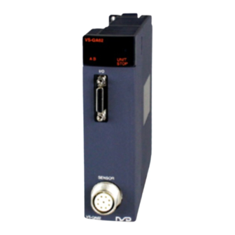
4.2 Name of Parts The illustration below shows the nomenclature of VS-QA62-V1PG. Operation status display area External I/O connector Sensor connector Functions of operation status display area Lower level "6" LED(Error LED) Switches on or blinks when an error occurs. (There is no error printing). Upper level 0 to F and lower level 0 LED VS-QA62... -
Page 32: Wiring Precautions
4.3 Wiring Precautions The wiring precautions for connections between VS-QA62-V1PG and external devices, and details regarding wiring connectors are explained in this section. 4.3.1 Wiring precautions The following wiring precautions should be observed when connecting VS-QA62-V1PG to external devices. (1) VS-QA62-V1PG signal lines and ABSOCODER sensor cable should be located as far as possible from power lines and other lines which generate a high level of electrical noise. -
Page 33: Absocoder Sensor Installation Precautions
4.4 ABSOCODER Sensor Installation Precautions This section explains precautions for ABSOCODER sensor installation. 4.4.1 Installation of ABSOCODER sensor ● Handling of Turn-type ABSOCODER sensor Item Explanation 1) Main unit 2) Cable ● Mounting of Turn-type ABSOCODER sensor Item Explanation Precaution For details regarding mounting dimensions, refer to each 1) Mounting ABSOCODER sensor dimensions. - Page 34 ● Mounting of Turn-type ABSOCODER sensor Item Explanation Precaution A “direct-link” format will 1) Coupling of machine result in shaft fatigue shaft and sensor and / or breakage after shaft long periods. Therefore, be sure to use a coupling device to link the shafts.
-
Page 35: Precautions When Connecting Absocoder Sensor
● Coupling of Turn-type ABSOCODER sensor Item Explanation Precaution 1. Selection of the coupling device should be based on the The selection of a 1) Coupling device following factors; larger coupling than selection precaution - The amount of a mounting error caused by the machine necessary will increase design. -
Page 36: Current Position Detection Function
5. CURRENT POSITION DETECTION FUNCTION 5. CURRENT POSITION DETECTION FUNCTION 5.1 Function Description This section explains VS-QA62-V1PG’s current position detection function. 5.1.1 Current position detection function VS-QA62-V1PG’s current position detection function detects the current position the ABSOCODER sensor. Conventionally, this was detected by an incremental format encoder in conjunction with a counter unit. As shown in Fig. -
Page 37: Current Position Setting Function
5.1.3 Current position setting function The current position setting is the function that the current position value of VS-QA62-V1PG is changed to a value which corresponds to the current machine angle. The current position setting value (Address 21) can be changed to a value which was previously designated through the buffer memory. -
Page 38: Switch Output Function
5.1.5 Switch output function The switch output function (SW 1 to 128) is described in this section. It outputs the ON/OFF signal to the external device instead of cam switch with detecting the machine position by the ABSOCODER sensor. ON/OFF position can be set your desirable one. The position which is detected by the ABSOCODE sensor is set to ON/OFF position as indicated in the figure 5.1.5 (2). - Page 39 5.1.5.1 Switch output setting The setting value is written in the switch output ON/OFF setting value storage area of the buffer memory (Address 22 to 277) when setting the switch output. Pay attention the following contents when writing the setting value. ①...
-
Page 40: Pulse Output Function
5.1.6 Pulse output function This section explains the pulse output function. The function outputs the pulse signal to the external device that 1 turn of the ABSOCODER sensor is divided equally. The number of pulses can be designated the desired value between 1 and 100. 現在値... -
Page 41: Programming
5.2 Programming This section explains how to create the sequence program using VS-QA62-V1PG. 5.2.1 Program creation precautions (1) VS-QA62-V1PG is an intelligent function module containing 32 exclusive input and output points. (2) In response to ‘FROM/TO’ instructions, the first input/output No. of VS-QA62-V1PG’s slot will be designated. -
Page 42: Program For Current Position Monitor Display
5.2.2 Program for current position monitor display A program example for the current position monitor display is given below. Conditions (1) The following signal assignments are used to control VS-QA62-V1PG: VS-QA62-V1PG ‘online’ command ··············································· X32 Current position (sensor binary) storage resister ····························· D0, D1 Current position (sensor binary) output to external display unit ···········... - Page 43 Explanation (1) When VS-QA62-V1PG is online, the ‘X1’ signal turns ON. (2) The current position value is readout from the buffer memory as follows : Buffer memory Address 0 (6 digits) Address 1 (DBCD instruction)
-
Page 44: Program For Error Code Readout And Reset
5.2.3 Program for error code readout and reset A program example for the error code readout and error reset operation which is used when a VS-QA62-V1PG ‘error detection’ occurs is given below. Conditions The following signal assignments are used to control VS-QA62-V1PG: Output for the external BCD display unit ···············... - Page 45 (2) Example of program using an intelligent function device (U ¥G │ X0032 │ 0├─┤ ├──────────────────────────────────────────(Y0010 )┤ │ On line command PLC ready │ │ of VS-QA62-V1PG │ │ │ │ │ │ │ │ X0004 │ 2├─┤ ├──────────────────────────────────────────(Y0061 )┤ Sensor error monitor output │...
-
Page 46: Program For Current Position Setting
5.2.4 Program for current position setting A program example for the current position setting is given below. Conditions (1) The following signal assignments are used to control VS-QA62-V1PG: VS-QA62-V1PG ‘online’ command ··············································· X32 ‘Current position setting’ command ··············································· X33 Current position setting value ······················································ X20 to X2F ‘Current position setting value’... -
Page 47: Program For Sensor Rotation Direction Setting
5.2.5 Program for sensor rotation direction setting A program example for the sensor rotation direction setting is given below. Conditions (1) The following signal assignments are used to control VS-QA62-V1PG: VS-QA62-V1PG ‘online’ command ··············································· X32 ‘Sensor rotation direction’ command ············································· X33 Rotation direction setting value ····················································... -
Page 48: Program For Switch Output Setting
5.2.6 Program for switch output setting A program example for the switch output setting is given below. Conditions (1) The following signal assignments are used to control VS-QA62-V1PG: VS-QA62-V1PG ‘online’ command ··············································· X32 ‘Switch data write’ command ······················································· X33 ‘Switch output setting value’ storage resister ·································· D5000 (2) The switch output setting value has already been stored at the data register. -
Page 49: Number Of Pulses Setting Program
5.2.7 Number of pulses setting program A program example for the number of pulses setting is indicated below. Conditions 1) The following signal assignments are used to control VS-QA62-V1PG: VS-QA62-V1PG ‘online’ command ·········································· X32 ‘Number of pulses write’ command ·········································· X33 Number of pulses setting value storage register ·························... -
Page 50: Troubleshooting
6. TROUBLESHOOTING 6. TROUBLESHOOTING VS-QA62-V1PG operation errors and troubleshooting procedures are described in this section. 6.1 Error Code List VS-QA62-V1PG error codes are described below. When VS-QA62-V1PG detects an error, the corresponding error code is stored at address 7 of the buffer memory. At that time the ‘error detection’ signal (X7) is turned ON. -
Page 51: Troubleshooting Flowchart
6.2 Troubleshooting Flowchart The VS-QA62-V1PG troubleshooting procedure is explained below. For CPU module related problems, consult the manual for the CPU module in question. Error Occurs If the signal doesn't go ON even when the CPU module is reset, a VS-QA62-V1PG Is VS-QA62-V1PG H/W (hardware) problem is likely. -
Page 52: Flowchart For No Switch Output From Vs-Qa62-V1Pg
6.3 Flowchart for No Switch Output from VS-QA62-V1PG No Switch output from VS-QA62-V1PG Note the error code, and check the causes. Is error detection signal (X7) ON or ERROR LED ON. Turn the VS-QA62-V1PG 'PLC ready' signal VS-QA62-V1PG 'Y10' signal ON? (Y10) ON. -
Page 53: Flowchart When External Origin Setting Is Impossible
6.4 Flowchart when External Origin Setting is Impossible External origin setting cannot be executed. Does an error Note the error code, and check the causes. status exist at the VS-QA62-V1PG? Turn the VS-QA62-V1PG 'PLC ready' signal ‘Online’ status established? (Y10) ON. Wire the external origin setting input signal External origin setting input signal line properly... -
Page 54: Flowchart When Current Position Setting Is Impossible
6.5 Flowchart when Current Position Setting is Impossible Current position setting cannot be executed. Does an error Note the error code, and check the causes. status exist at the VS-QA62-V1PG? Turn the VS-QA62-V1PG 'PLC ready' signal ‘Online’ status established? (Y10) ON. Is the current position Set the correct value. -
Page 55: Flowchart When Absocoder's Current Position Value Doesn't Change
6.6 Flowchart when ABSOCODER’s Current Position Value doesn’t Change ABSOCODER’s current position value doesn’t change. Does an error Note the error code, and check the causes. status exist at VS-QA62-V1PG? Rotate the ABSOCODER sensor. Does the ABSOCODER sensor rotate? Sensor to VS-QA62-V1PG Refer to section 4.3, and correct the cable cable connection... -
Page 56: Flowchart When Stored Data Is Lost, Or When Erroneous Data Is Stored
6.7 Flowchart when Stored Data is Lost, or when Erroneous Data is Stored Data is lost (deleted) or erroneous data is stored. Does an error Note the error code, and status exist at VS-QA62-V1PG? check the causes. Switch output data? Revise the sequence Has the data content been re-written at the sequence... - Page 57 MEMO...
-
Page 58: Appendix 1 Ce Marking
APPENDIX APPENDIX 1 CE Marking VS-QA62 series conforms to EMC directive, but stands outside scope of the low voltage directive. (1) EMC Directives It is necessary to do CE marking in the customer’s responsibility in the state of a final product. Confirm EMC compliance of the machine and the entire device by customer because EMC changes configuration of the control panel, wiring, and layout. -
Page 59: Appendix 2 Ul Standard
APPENDIX 2 UL STANDARD The VS-QA62 Series corresponds to the UL standard. Read this page carefully and use the VS-QA62 Series by following the described items. (1) Installation - Install inside the control cabinet. - For use in pollution degree 2 environment. - Within the surrounding air temperature 0℃... -
Page 60: Appendix 3 Kc Mark
APPENDIX 3 KC MARK Notification for users 사용자안내문 This product complied with the relevant Korean Safety Standard for use in the industrial environment. Thus, radio frequency interference could occur if it is used in a domestic environment. 이 기기는 업무용 환경에서 사용할 목적으로 적합성평가를 받은 기기로서 가정용... - Page 61 MEMO...
-
Page 62: Appendix 4 Absocoder Sensor Specifications
APPENDIX 4 ABSOCODER SENSOR SPECIFICATIONS Appendix 4.1 ABSOCODER Sensor for VS-QA62-V1PG Appendix 4.1.1 Specifications Item Specifications Sensor model VRE-P028 VRE-P062 Total number of turns Divisions 8192 (2 Mass 0.25 kg 1.3 kg Linearity error 1.5°Max. 1°Max. 9.3 X 10 kg・m 6.4 X 10 kg・m Moment of inertia... -
Page 63: Appendix 4.1.2 Absocoder Sensor Dimensions
Appendix 4.1.2 ABSOCODER sensor dimensions (1) VRE-P062SAC Units: mm (2) VRE-P062SBC (3) SH-01 (Reinforced servo-mount fixture for VRE-P062SAC / SBC) Option (2 pieces / 1set) - Page 64 (4) VRE-P062FAC Units: mm (5) VRE-P062FBC (6) RB-01 (L type flange-mount fixture) Option L type flange-mount fixture is for VRE-P062. Following combinations are able to use with. - VRE-P062SAC/SBC + SH-01 - VRE-P062FAC/FBC...
- Page 65 (7) VRE-P028SAC Units: mm...
-
Page 66: Appendix 4.2 Absocoder Cable
Appendix 4.2 ABSOCODER Cable VS-QA62-V1PG and ABSOCODER connector cable specifications are given below. Appendix 4.2.1 Specifications Items Specifications Model code 3P-S 3P-RBT Cable type Standard cable Robotic cable Diameter φ8 Operating -5 to +60°C -5 to +60°C Ambient temperature Storage -5 to +60°C -10 to +60°C Irradiated cross linked formed... -
Page 67: Appendix 4.2.4 Absocoder Cable Connection
Appendix 4.2.4 ABSOCODER Cable Connection ABSOCODER sensor VS-QA62-V1PG VRE-P062 Extension sensor cable VRE-P028 3P-S-0102-[L] 3P-RBT-0102-[L] 3P-S-0102-[L] 3P-S-0102-[L] 3P-RBT-0102-[L] 3P-RBT-0102-[L]... -
Page 68: Appendix 5 Dimensions
APPENDIX 5 DIMENSIONS Appendix 5.1 VS-QA62-V1PG Position Detection Module Units: mm... -
Page 69: Appendix 5.2 External I/O Cable (Vs-Cqa62)
Appendix 5.2 External I/O Cable (VS-CQA62) Units: mm ●VS-CQA62 2000 VS-QA62 side Shielded twisted pair cable HDR-E26MG1+ (Connector) Equivalent of UL20276, 13P x AWG28 (7/0.127) HDR-E26LPHP3+ (Cover) (HONDA TSUSHIN KOGYO CO., LTD.) VS-QA62 side Shi eld Signal name Pin No. Orange ■... -
Page 70: Appendix 5.3 Cable For The Upgrading (Vs-Cqa62-R01)
Appendix 5.3 Cable for the Upgrading (VS-CQA62-R01) Units: mm ●VS-CQA62-R01 VS-QA62 side Host side Shielded twisted pair cable Equivalent of UL20276, 13P x AWG28 (7/0.127) HDR-E26MG1+ (Connector) FCN-361P024-AU / N361P024AU (Connector) HDR-E26LPHP3+ (Cover) FCN-360C024-C / N360C024C (Cover) (HONDA TSUSHIN KOGYO CO., LTD) (FUJITSU COMPONENT LIMITED / OTAX CO., LTD.) VS-QA62 side Host side... - Page 71 MEMO...
-
Page 72: Appendix 6. Absocoder Check List
APPENDIX 6. ABSOCODER Check List ● Applicable ABSOCODER models VRE-P028 VRE-P062 ● Connection configuration ● Connector appearance and pin position Sensor cable ABSOCODER VS-QA62-V1PG sensor View A VRE-P062 VRE-P028 Checks at Point B should be carried out with Point A connected. ●... - Page 73 *1: If checks are done at Point B, the measurement value is [Standard coil resistance + extension sensor cable resistance (cable length (m) x 0.2 (Ω)]. The resistance value of the NSD special cable is 0.2Ω/m (loop resistance). Consider resistance variations due to temperature, which, relative to the standard temperature (25 C), increases 0.4% when the temperature rises 1...
-
Page 74: Appendix 7 I/O Signals And Buffer Memory Function List
APPENDIX 7 I/O SIGNALS and BUFFER MEMORY FUNCTION LIST ◯: Input/output enabled ×: Input/output disabled VS-QA62 (online/offline) Signal type Online Offline Remarks Signal No., Address, Pin No., & Name Unit ready [VS-QA62 detection] ○ ○ VS-QA62 operation status (online/offline) Signal inputs to PLC CPU ‘Sensor error’... -
Page 75: Appendix 8 Data Sheet
APPENDIX 8 DATA SHEET Appendix 8.1 Initial Setting Address Item Default Value Setting Value Sensor rotation direction (0: CW / 1: CCW) Current position setting value Setting range: 0 to 3599 Pulse output Setting range: 1 to 100... -
Page 76: Appendix 8.2 Switch Output
Appendix 8.2 Switch Output Switch Switch Switch name Address Setting value Switch name Address Setting value... - Page 77 Switch Switch Switch name Address Setting value Switch name Address Setting value...
- Page 78 Switch Switch name Address Setting value...
- Page 80 Manufacturer NSD Corporation 3-31-28, OSU, NAKA-KU, NAGOYA, JAPAN 460-8302 Distributor NSD Trading Corporation 3-31-23, OSU, NAKA-KU, NAGOYA, JAPAN 460-8302 Phone: +81-52-261-2352 Facsimile: +81-52-252-0522 URL: www.nsdcorp.com E-mail: foreign@nsdcorp.com Copyright©2024 NSD Corporation All rights reserved.
Need help?
Do you have a question about the MELSEC-Q VS-QA62-V1PG and is the answer not in the manual?
Questions and answers