Table of Contents
Advertisement
Quick Links
R-410A
AFFINITY SERIES
BHX024-060
General . . . . . . . . . . . . . . . . . . . . . . . . . . . . . . . . . . . . . . . . . . 1
Installation . . . . . . . . . . . . . . . . . . . . . . . . . . . . . . . . . . . . . . . . 3
Limitations . . . . . . . . . . . . . . . . . . . . . . . . . . . . . . . . . . . . . . 3
Location. . . . . . . . . . . . . . . . . . . . . . . . . . . . . . . . . . . . . . . . 4
Rigging And Handling . . . . . . . . . . . . . . . . . . . . . . . . . . . . . 4
Ductwork . . . . . . . . . . . . . . . . . . . . . . . . . . . . . . . . . . . . . . . 7
Roof Curb . . . . . . . . . . . . . . . . . . . . . . . . . . . . . . . . . . . . . . 7
Filters . . . . . . . . . . . . . . . . . . . . . . . . . . . . . . . . . . . . . . . . . 7
Condensate Drain . . . . . . . . . . . . . . . . . . . . . . . . . . . . . . . . 8
Service Access . . . . . . . . . . . . . . . . . . . . . . . . . . . . . . . . . . 8
Thermostat . . . . . . . . . . . . . . . . . . . . . . . . . . . . . . . . . . . . . 8
Power And Control Wiring. . . . . . . . . . . . . . . . . . . . . . . . . . 8
1 Unit Limitations . . . . . . . . . . . . . . . . . . . . . . . . . . . . . . . . . 3
2 Unit Accessory Weights . . . . . . . . . . . . . . . . . . . . . . . . . . 5
3 Unit Dimensions Front . . . . . . . . . . . . . . . . . . . . . . . . . . . . 5
4 Unit Clearances . . . . . . . . . . . . . . . . . . . . . . . . . . . . . . . . . 5
5 Electrical Data . . . . . . . . . . . . . . . . . . . . . . . . . . . . . . . . . 10
6 Physical Data . . . . . . . . . . . . . . . . . . . . . . . . . . . . . . . . . 11
7 Side Duct Application . . . . . . . . . . . . . . . . . . . . . . . . . . . 13
8 Bottom Duct Application . . . . . . . . . . . . . . . . . . . . . . . . . 15
1 Component Location . . . . . . . . . . . . . . . . . . . . . . . . . . . . 3
2 Unit 4 Point Load Weight . . . . . . . . . . . . . . . . . . . . . . . . . 4
3 Unit Dimensions . . . . . . . . . . . . . . . . . . . . . . . . . . . . . . . . 5
4 Dimensions Front and Bottom . . . . . . . . . . . . . . . . . . . . . 6
5 Dimensions Back and Bottom . . . . . . . . . . . . . . . . . . . . . 6
6 Roof Curb . . . . . . . . . . . . . . . . . . . . . . . . . . . . . . . . . . . . . 7
General
®
YORK
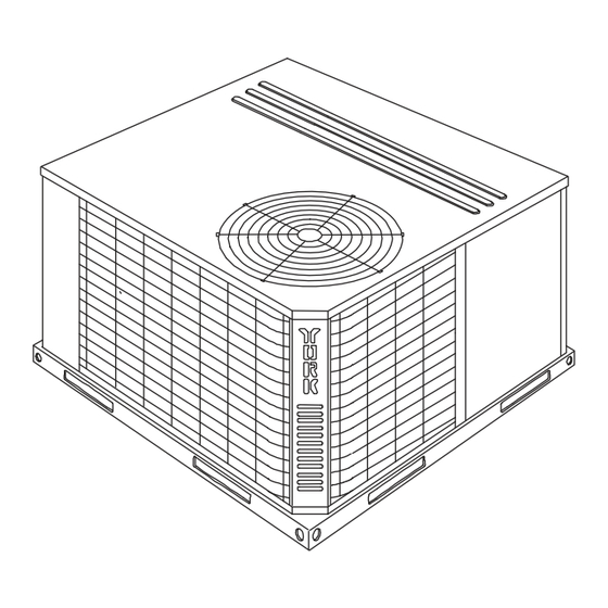
Affinity Model BHX units are factory assembled heat
pumps designed for outdoor installation on a roof top or a slab.
Field-installed electric heater accessories are available to
provide supplemental electric heat combined with electric
cooling and heating.
The units are completely assembled on rigid, removable base
rails. All piping, refrigerant charge, and electrical wiring is
factory installed and tested. The units require only electric
power and duct connections at the point of installation.
The electric heaters have nickel-chrome resistance wire
elements and utilize single point power connection.
Safety Considerations
This is a safety alert symbol
labels or in manuals, be alert to the potential for personal injury.
Understand and pay particular attention the signal words
DANGER, WARNING or CAUTION.
TABLE OF CONTENTS
LIST OF TABLES
LIST OF FIGURES
. When you see this symbol on
Compressors. . . . . . . . . . . . . . . . . . . . . . . . . . . . . . . . . . . 12
Phasing . . . . . . . . . . . . . . . . . . . . . . . . . . . . . . . . . . . . . . . 12
Airflow Performance . . . . . . . . . . . . . . . . . . . . . . . . . . . . . . . 13
Blower Speed Selection . . . . . . . . . . . . . . . . . . . . . . . . . . 18
Operation . . . . . . . . . . . . . . . . . . . . . . . . . . . . . . . . . . . . . . . 18
Cooling Sequence Of Operations . . . . . . . . . . . . . . . . . . . 18
Heating Sequence Of Operations . . . . . . . . . . . . . . . . . . . 19
Maintenance . . . . . . . . . . . . . . . . . . . . . . . . . . . . . . . . . . . . . 22
Normal Maintenance . . . . . . . . . . . . . . . . . . . . . . . . . . . . . 22
Troubleshooting . . . . . . . . . . . . . . . . . . . . . . . . . . . . . . . . . . 22
Wiring Diagrams . . . . . . . . . . . . . . . . . . . . . . . . . . . . . . . . 23
9 Additional Static Resistance . . . . . . . . . . . . . . . . . . . . . . 17
10 Electric Heat Minimum Supply Air . . . . . . . . . . . . . . . . . 17
11 Indoor Blower Specifications . . . . . . . . . . . . . . . . . . . . . . 17
12 Electric Heat Multipliers . . . . . . . . . . . . . . . . . . . . . . . . . 18
13 Delay Profile . . . . . . . . . . . . . . . . . . . . . . . . . . . . . . . . . . 18
14 Thermostat Signals (Single Phase Units) . . . . . . . . . . . . 20
15 Thermostat Signals (Three Phase Units) . . . . . . . . . . . . 21
9 Field Power Wiring Diagram . . . . . . . . . . . . . . . . . . . . . 10
10 Control Board Speed Tap Location . . . . . . . . . . . . . . . . 18
11 Demand Defrost "Curve" Selection Jumper . . . . . . . . . . 19
12 R-410A Quick Reference Guide . . . . . . . . . . . . . . . . . . 29
DANGER indicates an imminently hazardous situation, which,
if not avoided, will result in death or serious injury.
WARNING indicates a potentially hazardous situation, which,
if not avoided, could result in death or serious injury.
CAUTION indicates a potentially hazardous situation, which, if
not avoided may result in minor or moderate injury. It is also
used to alert against unsafe practices and hazards involving
only property damage.
Improper installation may create a condition where the
operation of the product could cause personal injury or
property damage. Improper installation, adjustment,
alteration, service or maintenance can cause injury or
property damage. Refer to this manual for assistance or
for additional information, consult a qualified contractor,
installer or service agency.
SO 9001
Certified Quality
Management System
155439-YIM-F-0211
Advertisement
Table of Contents

Related Manuals for Johnson Controls AFFINITY BHX024


Summary of Contents for Johnson Controls AFFINITY BHX024
-
Page 1: Table Of Contents
R-410A AFFINITY SERIES BHX024-060 SO 9001 2-5 Ton Certified Quality Management System TABLE OF CONTENTS General ......... . 1 Compressors. - Page 2 1 = New or Current Design A = No Electric Heat Installed Product Identifier Nominal Cooling Capacity (MBH) HX = R-410A 15 SEER 024 = 24,000 BTUH 048 = 48,000 BTUH 036 = 36,000 BTUH 060 = 60,000 BTUH Johnson Controls Unitary Products...
-
Page 3: Installation
Removable Base Rails Figure 1: Component Location Table 1: Unit Limitations Unit Limitations Size Unit Voltage Applied Voltage Outdoor DB Temp (Tons) Max (°F) 208/230-1-60 (2.0) 208/230-1-60 208/230-3-60 (3.0) 460-3-60 208/230-1-60 208/230-3-60 (4.0) 460-3-60 208/230-1-60 208/230-3-60 (5.0) 460-3-60 Johnson Controls Unitary Products... -
Page 4: Location
GRAVITY UNIT "A" "C" "B" 49-1/8 47-1/4 Figure 2: Unit 4 Point Load Weight Weight (lbs.) Center of Gravity 4 Point Load Location (lbs.) Size (Tons) Shipping Operating 22.25 (2.0) 21.75 24.25 (3.0) (4.0) 26.25 (5.0) Johnson Controls Unitary Products... -
Page 5: Unit Accessory Weights
For all other heaters, zero inch clearance all sides for entire length of duct. Note: For units applied with a roof curb, the minimum clearance may be reduced from 1 inch to 1/2 inch between combustible roof curb material and this supply air duct. Johnson Controls Unitary Products... -
Page 6: Dimensions Front And Bottom
SIDE SUPPLY 14-1/2 AIR OPENING *CONDENSER 28-3/8 COIL 14-1/2 BACK BOTTOM SUPPLY AIR OPENING 3-3/8 SIDE RETURN AIR OPENING 14-1/2 4-1/4 1-3/4 1-3/4 BOTTOM RETURN 28-9/16 3-1/2 AIR OPENING 1-3/4 Figure 5: Dimensions Back and Bottom Johnson Controls Unitary Products... -
Page 7: Ductwork
When fastening duct work to the side duct flanges on the unit, insert the screws through the duct flanges only. DO NOT insert the screws through the casing. Outdoor duct work must be insulated and waterproofed. 1. 8” Roof Curb also available. Johnson Controls Unitary Products... -
Page 8: Condensate Drain
Refer to Figures 7, 8 and 9 for typical field wiring and to the appropriate unit wiring diagram for control circuit and power wiring information. Johnson Controls Unitary Products... -
Page 9: Field Control Wiring Diagram Single Stage Thermostat . 9 8 Field Control Wiring Diagram 2 Stage Thermostat
TERMINAL STRIP ** = Minimum wire size of 18 AWG wire should be used for all field installed 24 volt wire. 24 VOLT TRANSFORMER PROGRAMMABLE THERMOSTAT ONLY Figure 8: Field Control Wiring Diagram 2 Stage Thermostat Johnson Controls Unitary Products... -
Page 10: Electrical Data
32.2 460-3-60 2NH04501546 39.7 2NH04502046 24.1 47.2 2NP04502546 30.1 54.7 1. Minimum Circuit Ampacity. 2. Maximum Over Current Protection per standard UL 1995. 3. Fuse or HACR circuit breaker size installed at factory or field installed. Johnson Controls Unitary Products... -
Page 11: Physical Data
Variable Variable Frame size FILTERS Quantity - Size 2 - 22 x 14 x 1 2 - 22 x 14 x 1 2 - 22 x 14 x 1 2 - 22 x 14 x 1 Johnson Controls Unitary Products... -
Page 12: Compressors
POE (polyolester) compressor lubricants are known to cause phasing to obtain the proper rotation. long term damage to some synthetic roofing materials. Scroll compressors require proper rotation to operate properly. Failure to check and correct rotation may result in property damage. Johnson Controls Unitary Products... -
Page 13: Side Duct Application
COOL-B; HEAT-D 1200 Y1+W1 COOL-C; HEAT-A 1200 Aux. Y1+W1 COOL-C; HEAT-B 1100 Heat Y1+W1 COOL-C; HEAT-C 1320 Y1+W1 COOL-C; HEAT-D 1200 Y1+W1 COOL-D; HEAT-A 1300 Y1+W1 COOL-D; HEAT-B 1300 Y1+W1 COOL-D; HEAT-C 1320 Y1+W1 COOL-D; HEAT-D 1300 Johnson Controls Unitary Products... - Page 14 COOL-B; HEAT-D 2070 Y1+W1 COOL-C; HEAT-A 1900 Aux. Y1+W1 COOL-C; HEAT-B 1975 Heat Y1+W1 COOL-C; HEAT-C 2150 Y1+W1 COOL-C; HEAT-D 2070 Y1+W1 COOL-D; HEAT-A 1900 Y1+W1 COOL-D; HEAT-B 1975 Y1+W1 COOL-D; HEAT-C 2150 Y1+W1 COOL-D; HEAT-D 2070 Johnson Controls Unitary Products...
-
Page 15: Bottom Duct Application
COOL-B; HEAT-D 1200 Y1+W1 COOL-C; HEAT-A 1200 Aux. Y1+W1 COOL-C; HEAT-B 1100 Heat Y1+W1 COOL-C; HEAT-C 1320 Y1+W1 COOL-C; HEAT-D 1200 Y1+W1 COOL-D; HEAT-A 1300 Y1+W1 COOL-D; HEAT-B 1300 Y1+W1 COOL-D; HEAT-C 1320 Y1+W1 COOL-D; HEAT-D 1300 Johnson Controls Unitary Products... - Page 16 COOL-B; HEAT-D 2070 Y1+W1 COOL-C; HEAT-A 1900 Aux. Y1+W1 COOL-C; HEAT-B 1975 Heat Y1+W1 COOL-C; HEAT-C 2150 Y1+W1 COOL-C; HEAT-D 2070 Y1+W1 COOL-D; HEAT-A 1900 Y1+W1 COOL-D; HEAT-B 1975 Y1+W1 COOL-D; HEAT-C 2150 Y1+W1 COOL-D; HEAT-D 2070 Johnson Controls Unitary Products...
-
Page 17: Ton
1430 1430 208/230-1-60 1615 1615 1955 1955 208/230-3-60 1615 1615 1955 1955 (5.0) 460-3-60 1615 1615 1955 1955 Table 11: Indoor Blower Specifications Size Motor (Tons) Eff. Frame Variable (2.0) Variable (3.0) Variable (4.0) Variable (5.0) Johnson Controls Unitary Products... -
Page 18: Blower Speed Selection
Power is supplied to heater installed. Find the desired airflow in Tables 7 and 8. Set the compressor and outdoor fan motor, and the reversing the “Heat” Jumper on the CFM selection board to tap shown. Johnson Controls Unitary Products... -
Page 19: Heating Sequence Of Operations
4-1/2 minutes, the heat pump is put into a Removing power from "R" for more than 2 seconds. defrost cycle. This 4-1/2 minute timer eliminates unnecessary Shorting the "TEST" pins together for more than 2 seconds. Johnson Controls Unitary Products... -
Page 20: Thermostat Signals (Single Phase Units)
HEATER BANK 3 ELEC. HEAT 20 SEC. DELAY ON HEATER BANK 3 ELEC. HEAT INSTANT OFF HEATER BANK 2 ELEC. HEAT 1/2 SEC. DELAY OFF HEATER BANK 1 ELEC. HEAT 1 SEC. DELAY OFF BLOWER 60 SEC. DELAY OFF Johnson Controls Unitary Products... -
Page 21: Thermostat Signals (Three Phase Units)
HEATER BANK 4, 5 & 6 ELEC. HEAT 10 SEC. DELAY ON HEATER BANK 4, 5 & 6 ELEC. HEAT INSTANT OFF HEATER BANK 1, 2 & 3 ELEC. HEAT 1/2 SEC. DELAY OFF BLOWER 60 SEC. DELAY OFF Johnson Controls Unitary Products... -
Page 22: Maintenance
Remove tab if present. Exercise care when cleaning the coil so that the coil fins are not damaged. Do not permit the hot condenser air discharge to be obstructed by overhanging structures or shrubs. Johnson Controls Unitary Products... -
Page 23: Wiring Diagrams
155439-YIM-F-0211 Wiring Diagrams BHX024, 048 and 060 Heat Pump 208/230-1-60 volt Wiring Diagram Johnson Controls Unitary Products... - Page 24 155439-YIM-F-0211 BHX036 Heat Pump 208/230-1-60 volt Wiring Diagram Johnson Controls Unitary Products...
- Page 25 155439-YIM-F-0211 BHX036 Heat Pump 230-3-60 volt Wiring Diagram Johnson Controls Unitary Products...
- Page 26 155439-YIM-F-0211 BHX048 and 060 Heat Pump 230-3-60 volt Wiring Diagram Johnson Controls Unitary Products...
- Page 27 155439-YIM-F-0211 BHX036 Heat Pump 460-3-60 volt Wiring Diagram Johnson Controls Unitary Products...
- Page 28 155439-YIM-F-0211 BHX048 and 060 Heat Pump 460-3-60 volt Wiring Diagram Johnson Controls Unitary Products...
-
Page 29: 410A Quick Reference Guide
Figure 12: R-410A Quick Reference Guide Subject to change without notice. Printed in U.S.A. 155439-YIM-F-0211 Copyright © 2011 by Johnson Controls, Inc. All rights reserved. Supersedes: 155439-YIM-E-0610 Johnson Controls Unitary Products 5005 York Drive Norman, OK 73069...
Need help?
Do you have a question about the AFFINITY BHX024 and is the answer not in the manual?
Questions and answers