Table of Contents
Advertisement
Quick Links
R-410A
AFFINITY SERIES
DEQ024-060
General . . . . . . . . . . . . . . . . . . . . . . . . . . . . . . . . . . . . . . . . . . 1
Installation . . . . . . . . . . . . . . . . . . . . . . . . . . . . . . . . . . . . . . . . 3
Limitations . . . . . . . . . . . . . . . . . . . . . . . . . . . . . . . . . . . . . . 3
Location. . . . . . . . . . . . . . . . . . . . . . . . . . . . . . . . . . . . . . . . 4
Rigging And Handling . . . . . . . . . . . . . . . . . . . . . . . . . . . . . 4
Ductwork . . . . . . . . . . . . . . . . . . . . . . . . . . . . . . . . . . . . . . . 7
Roof Curb . . . . . . . . . . . . . . . . . . . . . . . . . . . . . . . . . . . . . . 7
Filters . . . . . . . . . . . . . . . . . . . . . . . . . . . . . . . . . . . . . . . . . 7
Condensate Drain . . . . . . . . . . . . . . . . . . . . . . . . . . . . . . . . 7
Service Access . . . . . . . . . . . . . . . . . . . . . . . . . . . . . . . . . . 8
Thermostat . . . . . . . . . . . . . . . . . . . . . . . . . . . . . . . . . . . . . 8
Power And Control Wiring. . . . . . . . . . . . . . . . . . . . . . . . . . 8
1 Unit Limitations . . . . . . . . . . . . . . . . . . . . . . . . . . . . . . . . . 3
2 Unit Accessory Weights . . . . . . . . . . . . . . . . . . . . . . . . . . 5
3 Unit Dimensions Front . . . . . . . . . . . . . . . . . . . . . . . . . . . . 5
4 Unit Clearances . . . . . . . . . . . . . . . . . . . . . . . . . . . . . . . . . 5
5 Electrical Data . . . . . . . . . . . . . . . . . . . . . . . . . . . . . . . . . . 9
6 Physical Data . . . . . . . . . . . . . . . . . . . . . . . . . . . . . . . . . 11
7 Side Duct Application . . . . . . . . . . . . . . . . . . . . . . . . . . . 13
8 Bottom Duct Application . . . . . . . . . . . . . . . . . . . . . . . . . 14
9 Additional Static Resistance . . . . . . . . . . . . . . . . . . . . . . 15
10 Electric Heat Minimum Supply Air . . . . . . . . . . . . . . . . . . 16
1 Component Location . . . . . . . . . . . . . . . . . . . . . . . . . . . . 3
2 Unit 4 Point Load Weight . . . . . . . . . . . . . . . . . . . . . . . . . 4
3 Unit Dimensions . . . . . . . . . . . . . . . . . . . . . . . . . . . . . . . . 5
4 Dimensions Front and Bottom . . . . . . . . . . . . . . . . . . . . . 6
5 Dimensions Back and Bottom . . . . . . . . . . . . . . . . . . . . . 6
6 Roof Curb . . . . . . . . . . . . . . . . . . . . . . . . . . . . . . . . . . . . . 7
General
®
YORK
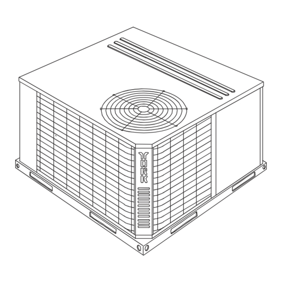
Affinity Model DEQ units are factory assembled cooling
units designed for outdoor installation on a roof top or a slab.
Field-installed electric heater accessories are available to
provide supplemental electric heat combined with electric
cooling.
The units are completely assembled on rigid, removable base
rails. All piping, refrigerant charge, and electrical wiring is
factory installed and tested. The units require only electric
power and duct connections at the point of installation.
The electric heaters have nickel-chrome resistance wire
elements and utilize single point power connection.
Safety Considerations
This is a safety alert symbol
labels or in manuals, be alert to the potential for personal injury.
Understand and pay particular attention the signal words
DANGER, WARNING or CAUTION.
TABLE OF CONTENTS
LIST OF TABLES
LIST OF FIGURES
. When you see this symbol on
Compressors. . . . . . . . . . . . . . . . . . . . . . . . . . . . . . . . . . . 12
Phasing . . . . . . . . . . . . . . . . . . . . . . . . . . . . . . . . . . . . . . . 12
Airflow Performance . . . . . . . . . . . . . . . . . . . . . . . . . . . . . . . 13
Blower Speed Selection . . . . . . . . . . . . . . . . . . . . . . . . . . 18
Operation . . . . . . . . . . . . . . . . . . . . . . . . . . . . . . . . . . . . . . . 19
Cooling Sequence Of Operations . . . . . . . . . . . . . . . . . . . 19
Heating Sequence Of Operations . . . . . . . . . . . . . . . . . . . 19
Maintenance . . . . . . . . . . . . . . . . . . . . . . . . . . . . . . . . . . . . . 20
Normal Maintenance . . . . . . . . . . . . . . . . . . . . . . . . . . . . . 20
Troubleshooting . . . . . . . . . . . . . . . . . . . . . . . . . . . . . . . . . . 20
Typical Wiring Diagrams . . . . . . . . . . . . . . . . . . . . . . . . . . 21
11 Indoor Blower Specifications . . . . . . . . . . . . . . . . . . . . . . 16
12 Electric Heat Multipliers . . . . . . . . . . . . . . . . . . . . . . . . . 16
13 DEQ024 Superheat Charging . . . . . . . . . . . . . . . . . . . . . 17
14 DEQ030 Superheat Charging . . . . . . . . . . . . . . . . . . . . . 17
15 DEQ036 Superheat Charging . . . . . . . . . . . . . . . . . . . . . 17
16 DEQ042 Superheat Charging . . . . . . . . . . . . . . . . . . . . . 17
17 DEQ048 Superheat Charging . . . . . . . . . . . . . . . . . . . . . 18
18 Delay Profile . . . . . . . . . . . . . . . . . . . . . . . . . . . . . . . . . . 18
19 Thermostat Signals (Single Phase Units) . . . . . . . . . . . . 19
20 Thermostat Signals (Three Phase Units) . . . . . . . . . . . . 20
7 Typical Field Control Wiring Diagram . . . . . . . . . . . . . . . 8
8 Typical Field Power Wiring Diagram . . . . . . . . . . . . . . . . 9
9 Control Board Speed Tap Location . . . . . . . . . . . . . . . . 18
10 R-410A Quick Reference Guide . . . . . . . . . . . . . . . . . . 27
DANGER indicates an imminently hazardous situation, which,
if not avoided, will result in death or serious injury.
WARNING indicates a potentially hazardous situation, which,
if not avoided, could result in death or serious injury.
CAUTION indicates a potentially hazardous situation, which, if
not avoided may result in minor or moderate injury. It is also
used to alert against unsafe practices and hazards involving
only property damage.
Improper installation may create a condition where the
operation of the product could cause personal injury or
property damage. Improper installation, adjustment,
alteration, service or maintenance can cause injury or
property damage. Refer to this manual for assistance or
for additional information, consult a qualified contractor,
installer or service agency.
SO 9001
Certified Quality
Management System
365780-YIM-B-0911
Advertisement
Table of Contents

Related Manuals for Johnson Controls DEQ024


Summary of Contents for Johnson Controls DEQ024
-
Page 1: Table Of Contents
3 Unit Dimensions Front ......5 13 DEQ024 Superheat Charging ..... 17 4 Unit Clearances . - Page 2 Reference Additional information is available in the following reference forms: • Technical Guide - DEQ024-060, 718433 Before performing service or maintenance operations on • General Installation - DEQ024-060, 365780 unit, turn off main power switch to unit. Electrical shock •...
-
Page 3: Installation
Table 1: Unit Limitations Unit Limitations Size Model Unit Voltage Applied Voltage Outdoor DB Temp (Tons) Max (°F) 208/230-1-60 (2.0) 208/230-1-60 (2.5) 208/230-1-60 208/230-3-60 (3.0) 460-3-60 208/230-1-60 208/230-3-60 (3.5) 460-3-60 208/230-1-60 208/230-3-60 (4.0) 460-3-60 208/230-1-60 208/230-3-60 (5.0) 460-3-60 Johnson Controls Unitary Products... -
Page 4: Location
49-1/8 47-1/4 Figure 2: Unit 4 Point Load Weight Size Weight (lbs.) Center of Gravity 4 Point Load Location (lbs.) Model (Tons) Shipping Operating 22.25 (2.0) 22.25 (2.5) 22.25 (3.0) 22.25 (3.5) 22.25 (4.0) 22.25 (5.0) Johnson Controls Unitary Products... -
Page 5: Unit Accessory Weights
For all other heaters, zero inch clearance all sides for entire length of duct. Note: For units applied with a roof curb, the minimum clearance may be reduced from 1 inch to 1/2 inch between combustible roof curb material and this supply air duct. Johnson Controls Unitary Products... -
Page 6: Dimensions Front And Bottom
SIDE SUPPLY 14-1/2 AIR OPENING *CONDENSER 28-3/8 COIL 14-1/2 BACK BOTTOM SUPPLY AIR OPENING 3-3/8 SIDE RETURN AIR OPENING 14-1/2 4-1/4 1-3/4 1-3/4 BOTTOM RETURN 28-9/16 3-1/2 AIR OPENING 1-3/4 Figure 5: Dimensions Back and Bottom Johnson Controls Unitary Products... -
Page 7: Ductwork
Use a sealing compound on male pipe threads. Install the DO NOT insert the screws through the casing. Outdoor condensate drain line (3/4” NPTF) to spill into an open drain. duct work must be insulated and waterproofed. 1. 8” Roof Curb also available. Johnson Controls Unitary Products... -
Page 8: Service Access
24 VOLT TRANSFORMER PROGRAMMABLE THERMOSTAT ONLY CAUTION: Label all wires prior to disconnection when servicing controls. Wiring errors cancause improper and dangerous operation. Verify proper operation after servicing. Figure 7: Typical Field Control Wiring Diagram Johnson Controls Unitary Products... -
Page 9: Electrical Data
15 / 20 41.7 / 48.1 60.6 / 68.6 70 / 70 2NH04502525 18.8 / 25 52.1 / 60.1 73.7 / 83.7 80 / 90 None 2NH04501046 19.3 460-3-60 2NH04501546 26.8 2NH04502046 24.1 34.3 2NH04502546 30.1 41.8 Johnson Controls Unitary Products... - Page 10 20.8 460-3-60 2NH04501546 28.3 2NH04502046 24.1 35.8 2NH04502546 30.1 43.3 1. Minimum Circuit Ampacity. 2. Maximum Over Current Protection per standard UL 1995. 3. Fuse or HACR circuit breaker size installed at factory or field installed. Johnson Controls Unitary Products...
-
Page 11: Physical Data
2 - 22 x 14 x 1 2 - 22 x 14 x 1 2 - 22 x 14 x 1 2 - 22 x 14 x 1 2 - 22 x 14 x 1 2 - 22 x 14 x 1 Johnson Controls Unitary Products... -
Page 12: Compressors
Exposure, even if immediately cleaned up, may cause embrittlement (leading to cracking) to occur in one year or more. When performing any service that may risk exposure of compressor oil to the roof, take precautions to protect roofing. Johnson Controls Unitary Products... -
Page 13: Side Duct Application
1700 (4.0) HEAT-A 1600 HEAT-B 1440 Heat HEAT-C 1760 HEAT-D 1600 COOL-A 1500 COOL-B 1650 Cool COOL-C 1800 1030 COOL-D 1900 1013 1072 (5.0) HEAT-A 1900 HEAT-B 1975 Heat HEAT-C 2150 1079 1154 HEAT-D 2070 1066 Johnson Controls Unitary Products... -
Page 14: Bottom Duct Application
1700 (4.0) HEAT-A 1600 HEAT-B 1440 Heat HEAT-C 1760 HEAT-D 1600 COOL-A 1500 COOL-B 1650 Cool COOL-C 1800 1030 COOL-D 1900 1013 1072 (5.0) HEAT-A 1900 HEAT-B 1975 Heat HEAT-C 2150 1079 1154 HEAT-D 2070 1066 Johnson Controls Unitary Products... -
Page 15: Additional Static Resistance
1. The pressure drop through the economizer is greater for 100% outdoor air than for 100% return air. If the resistance of the return air duct is less than 0.25 IWG, the unit will deliver less CFM during full economizer operation. Johnson Controls Unitary Products... -
Page 16: Ton
(2.0) 0.92 0.92 Variable (2.5) 1. Electric heaters are rated at nominal voltage. Use this table to Variable (3.0) determine the electric heat capacity for heaters applied at lower voltages. Variable (3.5) Variable (4.0) Variable (5.0) Johnson Controls Unitary Products... -
Page 17: Deq024 Superheat Charging
365780-YIM-B-0911 Table 13: DEQ024 Superheat Charging Superheat at Compressor Suction (°F), Airflow = 800 CFM Outdoor Temp Indoor Wet Bulb Temp (°F) (°F) 18.3 19.5 20.7 21.9 23.2 24.4 25.6 26.4 27.3 27.7 28.1 16.3 17.5 18.7 19.9 21.1 22.3 23.6... -
Page 18: Blower Speed Selection
18 for the regional climate in your area. Place the “DELAY” Jumper at “A” Standard Setting jumper tap on the CFM selection board to the appropriate pin Jumper at “B” Humid Climate setting. Jumper at “C” Dry Climate Jumper at “D” Temperate Climate Johnson Controls Unitary Products... -
Page 19: Operation
HEATER BANK 3 ELEC. HEAT 20 SEC. DELAY ON HEATER BANK 3 ELEC. HEAT INSTANT OFF HEATER BANK 2 ELEC. HEAT 1/2 SEC. DELAY OFF HEATER BANK 1 ELEC. HEAT 1 SEC. DELAY OFF BLOWER 60 SEC. DELAY OFF Johnson Controls Unitary Products... -
Page 20: Maintenance
The wire number or color and terminal designations referred to may vary. Check the wiring label inside the control box access panel for the correct wiring. Johnson Controls Unitary Products... -
Page 21: Typical Wiring Diagrams
365780-YIM-B-0911 Typical Wiring Diagrams Typical DEQ024-048 Cooling Only 208/230-1-60 volt Wiring Diagram Johnson Controls Unitary Products... - Page 22 365780-YIM-B-0911 Typical DEQ060 Cooling Only 208/230-1-60 volt Wiring Diagram Johnson Controls Unitary Products...
- Page 23 365780-YIM-B-0911 Typical DEQ036-048 Cooling Only 208/230-3-60 volt Wiring Diagram Johnson Controls Unitary Products...
- Page 24 365780-YIM-B-0911 Typical DEQ060 Cooling Only 208/230-3-60 volt Wiring Diagram Johnson Controls Unitary Products...
- Page 25 365780-YIM-B-0911 Typical DEQ036-048 Cooling Only 460-3-60 volt Wiring Diagram Johnson Controls Unitary Products...
- Page 26 365780-YIM-B-0911 Typical DEQ060 Cooling Only 460-3-60 volt Wiring Diagram Johnson Controls Unitary Products...
-
Page 27: 410A Quick Reference Guide
Figure 10: R-410A Quick Reference Guide Subject to change without notice. Printed in U.S.A. 365780-YIM-B-0911 Copyright © 2011 by Johnson Controls, Inc. All rights reserved. Supersedes: 365780-YIM-A-0508 Johnson Controls Unitary Products 5005 York Drive Norman, OK 73069...
Need help?
Do you have a question about the DEQ024 and is the answer not in the manual?
Questions and answers