Johnson Controls AFFINITY Series Installation Manual
R-410a 2-5 ton
Hide thumbs
Also See for AFFINITY Series:
- Installation manual (24 pages) ,
- Installation manual (27 pages) ,
- Installation manual (29 pages)
Table of Contents
Advertisement
Quick Links
R-410A
AFFINITY™ SERIES
DNY024-060
2-5 Ton
General . . . . . . . . . . . . . . . . . . . . . . . . . . . . . . . . . . . . . . . . . . 1
Installation . . . . . . . . . . . . . . . . . . . . . . . . . . . . . . . . . . . . . . . . 3
Limitations . . . . . . . . . . . . . . . . . . . . . . . . . . . . . . . . . . . . 3
Location. . . . . . . . . . . . . . . . . . . . . . . . . . . . . . . . . . . . . . . . 5
Rigging And Handling . . . . . . . . . . . . . . . . . . . . . . . . . . . . . 5
Ductwork . . . . . . . . . . . . . . . . . . . . . . . . . . . . . . . . . . . . . . . 9
Roof Curb . . . . . . . . . . . . . . . . . . . . . . . . . . . . . . . . . . . . . . 9
Filters . . . . . . . . . . . . . . . . . . . . . . . . . . . . . . . . . . . . . . . . . 9
Condensate Drain . . . . . . . . . . . . . . . . . . . . . . . . . . . . . . . 10
Service Access . . . . . . . . . . . . . . . . . . . . . . . . . . . . . . . . . 10
Thermostat . . . . . . . . . . . . . . . . . . . . . . . . . . . . . . . . . . . . 10
Power And Control Wiring. . . . . . . . . . . . . . . . . . . . . . . . . 10
Compressors. . . . . . . . . . . . . . . . . . . . . . . . . . . . . . . . . . . 16
1 Unit Limitations . . . . . . . . . . . . . . . . . . . . . . . . . . . . . . . . . 4
2 Weights and Dimensions . . . . . . . . . . . . . . . . . . . . . . . . . 6
3 Unit Accessory Weights . . . . . . . . . . . . . . . . . . . . . . . . . . 6
4 Unit Dimensions Front . . . . . . . . . . . . . . . . . . . . . . . . . . . . 7
5 Unit Clearances . . . . . . . . . . . . . . . . . . . . . . . . . . . . . . . . 7
6 Electrical Data . . . . . . . . . . . . . . . . . . . . . . . . . . . . . . . . . 13
7 Single Stage Physical Data . . . . . . . . . . . . . . . . . . . . . . . 14
8 Two Stage Physical Data . . . . . . . . . . . . . . . . . . . . . . . . 15
9 Natural Gas Pipe Sizing Chart . . . . . . . . . . . . . . . . . . . . 17
10 Propane (LP) Gas Pipe Sizing Chart . . . . . . . . . . . . . . . 17
11 Natural Gas Application Data-Single Stage . . . . . . . . . . 18
1 Component Location . . . . . . . . . . . . . . . . . . . . . . . . . . . . 4
2 Unit 4 Point Load Weight . . . . . . . . . . . . . . . . . . . . . . . . . 6
3 Unit Dimensions . . . . . . . . . . . . . . . . . . . . . . . . . . . . . . . . 7
4 Dimensions Front and Bottom . . . . . . . . . . . . . . . . . . . . . 8
5 Dimensions Back and Bottom . . . . . . . . . . . . . . . . . . . . . 8
6 Roof Curb . . . . . . . . . . . . . . . . . . . . . . . . . . . . . . . . . . . . . 9
Thermostat - Single Stage Gas Heat . . . . . . . . . . . . . . . 11
Thermostat - Two Stage Gas Heat . . . . . . . . . . . . . . . . 11
Thermostat - Single Stage Gas Heat . . . . . . . . . . . . . . . 12
General
®
YORK
Affinity Model DNY units are cooling/heating air
conditioners designed for outdoor installation. Only gas piping,
electric power and duct connections are required at the point of
installation.
The single or two stage gas-fired heaters have spark to pilot
ignition. The tubular heat exchangers are aluminized steel.
The refrigerant system is fully charged with R-410A Refrigerant,
and is tested and factory sealed.
TABLE OF CONTENTS
Phasing . . . . . . . . . . . . . . . . . . . . . . . . . . . . . . . . . . . . . . . 16
Gas Heat . . . . . . . . . . . . . . . . . . . . . . . . . . . . . . . . . . . . . . 16
Flue Vent Hood . . . . . . . . . . . . . . . . . . . . . . . . . . . . . . . . . 17
Airflow Performance . . . . . . . . . . . . . . . . . . . . . . . . . . . . . . . 19
Blower Speed Selection . . . . . . . . . . . . . . . . . . . . . . . . . . 24
Operation . . . . . . . . . . . . . . . . . . . . . . . . . . . . . . . . . . . . . . . 24
Heating Sequence Of Operation . . . . . . . . . . . . . . . . . . . . 24
Cooling Sequence Of Operations . . . . . . . . . . . . . . . . . . . 26
Start-Up . . . . . . . . . . . . . . . . . . . . . . . . . . . . . . . . . . . . . . . . . 27
Adjustment of Temperature Rise . . . . . . . . . . . . . . . . . . . 29
Checking Gas Heat Input . . . . . . . . . . . . . . . . . . . . . . . . . . . 29
Natural Gas . . . . . . . . . . . . . . . . . . . . . . . . . . . . . . . . . . . . 29
Typical Wiring Diagrams . . . . . . . . . . . . . . . . . . . . . . . . . . . . 30
LIST OF TABLES
12 Natural Gas Application Data-Two Stage . . . . . . . . . . . . 18
13 Propane (LP) Gas Application Data-Single Stage . . . . . 18
14 Propane (LP) Gas Application Data-Two Stage . . . . . . . 18
15 Side Duct Application . . . . . . . . . . . . . . . . . . . . . . . . . . . 19
16 Bottom Duct Application . . . . . . . . . . . . . . . . . . . . . . . . . 21
17 Additional Static Resistance . . . . . . . . . . . . . . . . . . . . . . 23
18 Indoor Blower Specifications . . . . . . . . . . . . . . . . . . . . . . 24
19 Delay Profile . . . . . . . . . . . . . . . . . . . . . . . . . . . . . . . . . . 24
20 Ignition Control Board FLASH CODES . . . . . . . . . . . . . . 26
21 Gas Rate Cubic Feet Per Hour . . . . . . . . . . . . . . . . . . . . 29
LIST OF FIGURES
Thermostat - Two Stage Gas Heat . . . . . . . . . . . . . . . . 12
11 Typical Field Power Wiring Diagram . . . . . . . . . . . . . . . 13
12 External Supply Connection External Shut-Off . . . . . . . 16
13 Flue Vent Outlet Air Hood . . . . . . . . . . . . . . . . . . . . . . . 17
14 Control Board Speed Tap Location . . . . . . . . . . . . . . . . 24
15 Single Stage Gas Valve Front . . . . . . . . . . . . . . . . . . . . 28
16 Two Stage Gas Valve Front . . . . . . . . . . . . . . . . . . . . . . 28
17 Single Stage Gas Valve Rear . . . . . . . . . . . . . . . . . . . . 28
18 Two Stage Gas Valve Rear . . . . . . . . . . . . . . . . . . . . . . 28
19 Proper Flame Adjustment . . . . . . . . . . . . . . . . . . . . . . . 28
20 R-410A Quick Reference Guide . . . . . . . . . . . . . . . . . . 42
Safety Considerations
This is a safety alert symbol
labels or in manuals, be alert to the potential for personal injury.
Understand and pay particular attention the signal words
DANGER, WARNING or CAUTION.
DANGER indicates an imminently hazardous situation, which,
if not avoided, will result in death or serious injury.
WARNING indicates a potentially hazardous situation, which,
if not avoided, could result in death or serious injury.
CAUTION indicates a potentially hazardous situation, which, if
not avoided may result in minor or moderate injury. It is also
used to alert against unsafe practices and hazards involving
only property damage.
SO 9001
Certified Quality
Management System
. When you see this symbol on
277832-YIM-E-0610
Advertisement
Table of Contents

Related Manuals for Johnson Controls AFFINITY Series


Summary of Contents for Johnson Controls AFFINITY Series
-
Page 1: Table Of Contents
R-410A AFFINITY™ SERIES DNY024-060 SO 9001 Certified Quality 2-5 Ton Management System TABLE OF CONTENTS General ......... . 1 Phasing . - Page 2 For use as a cooling only unit, cooling unit with Installation and service must be performed by a qualified supplemental electric heat or a forced air furnace. installer, service agency or the gas supplier. For outdoor installation only. Johnson Controls Unitary Products...
-
Page 3: Installation
Latest Edition Page 18 of these instructions. Local building codes, and This equipment is not to be used for temporary heating of Local gas utility requirements buildings or structures under construction. Johnson Controls Unitary Products... -
Page 4: Unit Limitations
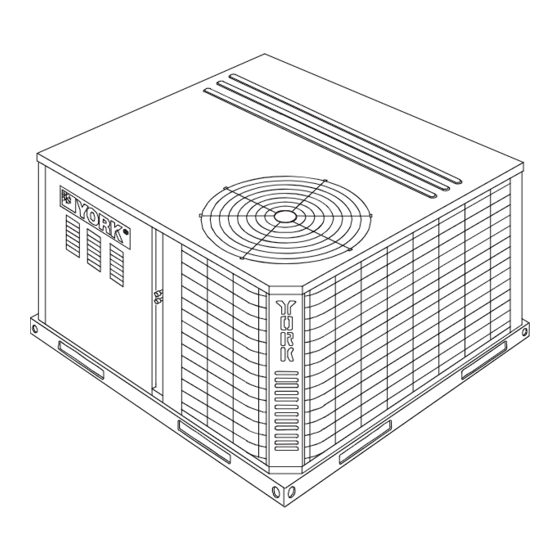
Terminal Block Figure 1: Component Location Table 1: Unit Limitations Unit Limitations Size Unit Voltage Applied Voltage Outdoor DB Temp (Tons) Max (°F) 208/230-1-60 (2.0) 208/230-1-60 208/230-3-60 (3.0) 460-3-60 208/230-1-60 208/230-3-60 (4.0) 460-3-60 208/230-1-60 208/230-3-60 (5.0) 460-3-60 Johnson Controls Unitary Products... -
Page 5: Location
The condenser coils should be protected from rigging 7.3, or 7.4 of Gas Installation Codes, CSA-B149.1 (in Canada) - cable damage with plywood or other suitable material. Latest Edition, and/or applicable provisions of the local building Johnson Controls Unitary Products... -
Page 6: Weights And Dimensions
Table 2: Weights and Dimensions Size Weight (lbs.) Center of Gravity 4 Point Load Location (lbs.) (Tons) Shipping Operating 24.5 (2.0) 24.25 (3.0) (4.0) (5.0) Table 3: Unit Accessory Weights Weight (lbs.) Unit Accessory Model Shipping Operating Add Economizer Johnson Controls Unitary Products... -
Page 7: Unit Dimensions Front
3. Units must be installed outdoors. Over hanging structure or shrubs should not obscure condenser air discharge outlet. 4. Units may be installed on combustable floors made from wood or class A, B or C roof covering materials. Johnson Controls Unitary Products... -
Page 8: Dimensions Front And Bottom
SIDE SUPPLY 14-1/2 AIR OPENING *CONDENSER 28-3/8 COIL 14-1/2 BACK BOTTOM SUPPLY AIR OPENING 3-3/8 SIDE RETURN AIR OPENING 14-1/2 4-1/4 1-3/4 1-3/4 BOTTOM RETURN 28-9/16 3-1/2 AIR OPENING 1-3/4 Figure 5: Dimensions Back and Bottom Johnson Controls Unitary Products... -
Page 9: Ductwork
Filters should be checked monthly; this is especially important NOTE: Be sure to note supply and return openings. since this unit is used for both heating and cooling. 1. 8” Roof Curb also available. Johnson Controls Unitary Products... -
Page 10: Condensate Drain
Refer to Figures 7 thru 11 for typical field wiring and to the appropriate unit wiring diagram for control circuit and power wiring information. Johnson Controls Unitary Products... -
Page 11: Typical Field Control Wiring Diagram Single Stage Thermostat - Single Stage Gas Heat
JUMPER NEEDED FOR FULL SPEED installed 24 volt wire. COMPRESSOR OPERATION 24 VOLT TRANSFORMER PROGRAMMABLE THERMOSTAT ONLY Figure 8: Typical Field Control Wiring Diagram Single Stage Thermostat - Two Stage Gas Heat Johnson Controls Unitary Products... -
Page 12: Typical Field Control Wiring Diagram Two Stage Thermostat - Single Stage Gas Heat
** = Minimum wire size of 18 AWG wire should be used for all field installed 24 volt wire. 24 VOLT TRANSFORMER PROGRAMMABLE THERMOSTAT ONLY Figure 10: Typical Field Control Wiring Diagram Two Stage Thermostat - Two Stage Gas Heat Johnson Controls Unitary Products... -
Page 13: Electrical Data
13.5 208/230-1-60 25.6 42.9 208/230-3-60 17.6 32.9 (5.0) 460-3-60 16.8 1. Minimum Circuit Ampacity. 2. Maximum Over Current Protection per standard UL 1995. 3. Fuse or HACR circuit breaker size installed at factory or field installed. Johnson Controls Unitary Products... -
Page 14: Single Stage Physical Data
Variable Variable Frame size FILTERS Quantity - Size 1 - 20 x 20 x 1 1 - 20 x 20 x 1 2 - 20 x 12 x 1 2 - 20 x 12 x 1 Johnson Controls Unitary Products... -
Page 15: Two Stage Physical Data
Variable Variable Frame size FILTERS Quantity - Size 1 - 20 x 20 x 1 1 - 20 x 20 x 1 2 - 20 x 12 x 1 2 - 20 x 12 x 1 Johnson Controls Unitary Products... -
Page 16: Compressors
If the scroll is drawing low amperage, has similar suction and discharge pressures, or is producing a high noise level, the scroll is misphased. Change the incoming line connection DRIP LEG phasing to obtain the proper rotation. Figure 12: External Supply Connection External Shut-Off Johnson Controls Unitary Products... -
Page 17: Natural Gas Pipe Sizing Chart
The gas supply should be a separate line and installed in cycle. Flue hood surface and the immediate area reach accordance with all safety codes as prescribed under high temperatures during the heating cycle. Limitations, shown on Page 3. After the gas connections Johnson Controls Unitary Products... -
Page 18: Natural Gas Application Data-Single Stage
4% for each 1,000 feet above sea level. 3. Based on 2500 BTU/Ft. 4. The air flow must be adequate to obtain a temperature rise within the range shown. Continuous return air temperature should not be below 55°F. Johnson Controls Unitary Products... -
Page 19: Airflow Performance
HEAT-B 1300 W1+W2 HEAT-C 1400 W1+W2 HEAT-D 1480 COOL-A 1030 COOL-B COOL-C 1070 COOL-D 1130 Cool (4.0) Y1+Y2 COOL-A 1550 1053 Y1+Y2 COOL-B 1400 High Y1+Y2 COOL-C 1600 1052 1116 Y1+Y2 COOL-D 1700 1049 1116 1185 Johnson Controls Unitary Products... - Page 20 W1+W2 HEAT-C 1500 W1+W2 HEAT-D 1600 HEAT-A 1450 HEAT-B 1500 N110 HEAT-C 1600 HEAT-D 1700 1049 HEAT-A HEAT-B HEAT-C 1035 HEAT-D 1100 D110 W1+W2 HEAT-A 1450 W1+W2 HEAT-B 1500 W1+W2 HEAT-C 1600 W1+W2 HEAT-D 1700 1049 Johnson Controls Unitary Products...
-
Page 21: Bottom Duct Application
HEAT-B 1300 W1+W2 HEAT-C 1400 W1+W2 HEAT-D 1480 COOL-A 1030 COOL-B COOL-C 1070 COOL-D 1130 Cool (4.0) Y1+Y2 COOL-A 1550 1053 Y1+Y2 COOL-B 1400 High Y1+Y2 COOL-C 1600 1052 1116 Y1+Y2 COOL-D 1700 1049 1116 1185 Johnson Controls Unitary Products... - Page 22 W1+W2 HEAT-C 1500 W1+W2 HEAT-D 1600 HEAT-A 1450 HEAT-B 1500 N110 HEAT-C 1600 HEAT-D 1700 1049 HEAT-A HEAT-B HEAT-C 1035 HEAT-D 1100 D110 W1+W2 HEAT-A 1450 W1+W2 HEAT-B 1500 W1+W2 HEAT-C 1600 W1+W2 HEAT-D 1700 1049 Johnson Controls Unitary Products...
-
Page 23: Additional Static Resistance
1. The pressure drop through the economizer is greater for 100% outdoor air than for 100% return air. If the resistance of the return air duct is less than 0.25 IWG, the unit will deliver less CFM during full economizer operation. Johnson Controls Unitary Products... -
Page 24: Blower Speed Selection
This cycle continues indefinitely until either the the cooling system CFM. This connection is factory set from the pressure switch is proved closed, or the call for heat ends. manufacturer, but can be field adjusted. Johnson Controls Unitary Products... - Page 25 The control board keeps the pilot gas valve, main gas valve and after 60 minutes. induced draft motor energized while continuously monitoring the call for heat, low pressure switch, and flame status. Lockouts due to detected internal control faults will reset after 60 minutes or power interruption. Johnson Controls Unitary Products...
-
Page 26: Cooling Sequence Of Operations
24VAC power to the control. If problem persist outdoor fan. The indoor blower will remain on according to the after removal and reapplication of 24VAC power, the board may fan delay profile selected using Table 19. need to be replaced. Johnson Controls Unitary Products... -
Page 27: Start-Up
Small adjustments to the gas flow may be made by turning the Operating Instructions pressure regulator adjusting screw on the automatic gas valve. Refer to Figures 15 and 16. STOP! Read the information on the unit safety label. Johnson Controls Unitary Products... -
Page 28: Single Stage Gas Valve Front
To adjust the pilot flame: " min. Manifold Pressure Adjustment (Under Cap) Line Pressure Tap (1/8” NPT) 1/2” NPT Spark Ignitor (Inlet) Pilot Flame Sensor Figure 17: Single Stage Gas Valve Rear Figure 19: Proper Flame Adjustment Johnson Controls Unitary Products... -
Page 29: Adjustment Of Temperature Rise
Turn off all other gas appliances connected to the gas meter. to the 100,000 BTUH rating of the furnace. With the furnace turned on, measure the time needed for one revolution of the hand on the smallest dial on the Johnson Controls Unitary Products... -
Page 30: Typical Wiring Diagrams
277832-YIM-E-0610 Typical Wiring Diagrams Typical DNY024-048 Cooling Unit with Single Stage Gas Heat 208/230-1-60 volt Wiring Diagram Johnson Controls Unitary Products... - Page 31 277832-YIM-E-0610 Typical DNY024-048 Cooling Unit with Two Stage Gas Heat 208/230-1-60 volt Wiring Diagram Johnson Controls Unitary Products...
- Page 32 277832-YIM-E-0610 Typical DNY060 Cooling Unit with Single Stage Gas Heat 208/230-1-60 volt Wiring Diagram Johnson Controls Unitary Products...
- Page 33 277832-YIM-E-0610 Typical DNY060 Cooling Unit with Two Stage Gas Heat 208/230-1-60 volt Wiring Diagram Johnson Controls Unitary Products...
- Page 34 277832-YIM-E-0610 Typical DNY036-048 Cooling Unit with Single Stage Gas Heat 208/230-3-60 volt Wiring Diagram Johnson Controls Unitary Products...
- Page 35 277832-YIM-E-0610 Typical DNY036-048 Cooling Unit with Two Stage Gas Heat 208/230-3-60 volt Wiring Diagram Johnson Controls Unitary Products...
- Page 36 277832-YIM-E-0610 Typical DNY060 Cooling Unit with Single Stage Gas Heat 208/230-3-60 volt Wiring Diagram Johnson Controls Unitary Products...
- Page 37 277832-YIM-E-0610 Typical DNY060 Cooling Unit with Two Stage Gas Heat 208/230-3-60 volt Wiring Diagram Johnson Controls Unitary Products...
- Page 38 277832-YIM-E-0610 Typical DNY036-048 Cooling Unit with Single Stage Gas Heat 460-3-60 volt Wiring Diagram Johnson Controls Unitary Products...
- Page 39 277832-YIM-E-0610 Typical DNY036-048 Cooling Unit with Two Stage Gas Heat 460-3-60 volt Wiring Diagram Johnson Controls Unitary Products...
- Page 40 277832-YIM-E-0610 Typical DNY060 Cooling Unit with Single Stage Gas Heat 460-3-60 volt Wiring Diagram Johnson Controls Unitary Products...
- Page 41 277832-YIM-E-0610 Typical DNY060 Cooling Unit with Two Stage Gas Heat 460-3-60 volt Wiring Diagram Johnson Controls Unitary Products...
-
Page 42: 410A Quick Reference Guide
Figure 20: R-410A Quick Reference Guide Subject to change without notice. Printed in U.S.A. 277832-YIM-E-0610 Copyright © 2010 by Johnson Controls, Inc. All rights reserved. Supersedes: 277832-YIM-D-0909 Johnson Controls Unitary Products 5005 York Drive Norman, OK 73069...
Need help?
Do you have a question about the AFFINITY Series and is the answer not in the manual?
Questions and answers