Pepperl+Fuchs 6000 SERIES Installation And Operation Manual
Purge/pressurization system
Hide thumbs
Also See for 6000 SERIES:
- Instruction manual (2 pages) ,
- Manual (72 pages) ,
- Installation and operation manual (72 pages)

Related Manuals for Pepperl+Fuchs 6000 SERIES


Summary of Contents for Pepperl+Fuchs 6000 SERIES
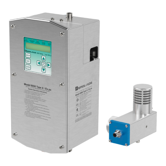
- Page 1 PROCESS AUTOMATION INSTALLATION AND OPERATION MANUAL 6000 SERIES PURGE/PRESSURIZATION SYSTEM...
- Page 2 6000 Series Purge/Pressurization System I/O Manual With regard to the supply of products, the current issue of the following document is applicable: The General Terms of Delivery for Products and Services of the Electrical Industry, published by the Central Association of the Electrical Industry (Zentralverband Elektrotechnik und Elektroindustrie (ZVEI) e.V.) in its most recent version as...
-
Page 3: Table Of Contents
Sequence of events ......................... 23 Turning on power to the enclosure ....................23 Turning off power to the enclosure ....................24 Operation of the 6000 series and component kit ..............25 Operation ............................25 Set-up procedures of 6000 series system ..................29 Operation of the 6000 series system .....................29 Start-up label located on 6000 series control unit ...............30... - Page 4 I/O Manual Fault ..............................43 Clear statistics ..........................44 Clear fault ............................44 Operation screen ..........................44 System dimensions ......................... 45 6000 series control unit ........................45 EPV-6000 vent ..........................46 6000 series component kit ......................47 Temperature hub ..........................48 Temperature sensor ........................49 6000 Manifold ...........................50 General specifications ......................51 Model number designators .....................
-
Page 5: Safety Note And Symbols Used
6000 Series Purge/Pressurization System I/O Manual Safety note and symbols used It is strongly urged that you follow all instructions and recommendations in this manual, in addition to all applicable codes, standards, and local requirements. Failure to do so voids all warranties, both implicit and explicit, and relieves the manufacturer of all liability. -
Page 6: General Instructions Regarding Atex
6000 Series Purge/Pressurization System I/O Manual General instructions regarding ATEX 4. General information about pressurized enclosures The pressurized enclosure is one of the most 1. The guidelines multifunctional applicable types of protection. It is based on a first flush operation which removes potential,... -
Page 7: Certification Information
6000 Series Purge/Pressurization System I/O Manual Certification information Marking for the 6000 control unit, 6000-__-S2-__-CK-__ Marking for the 6000 Control unit, 6000-__-S2-UN-WH-__ and 6000-__-S2-__-XD-__ Marking for the 6000 user interface controller, 6000-UIC-01 Marking for the 6000 vent, EPV-6000-__-__ Marking for the 6000-ISB-___ termination board,... -
Page 8: Warning Labels
6000 Series Purge/Pressurization System I/O Manual Warning Labels 8. The non-metallic membrane touchpad and display is a potential electrostatic discharge hazard. Use only water damp cloth and allow to air dry for cleaning WARNING - Conduit seal must be installed within 18 device. -
Page 9: Purpose
The 6000 series provides a complete system for purging Description and pressurizing enclosures for hazardous location The 6000 series Type X & Ex px purge and operation. pressurization system protects general purpose equipment mounted in a standard enclosure. This allows... -
Page 10: 6000 Control Unit
6000 Series Purge/Pressurization System I/O Manual 6000 Control Unit Main unit Bracket for mounting to the enclosure I.S. wiring terminals User interface controller (UIC) Removable electronics Explosion-proof/flameproof enclosure 3/4" conduit for power connections Cable glands for I.S. inputs/outputs 316L stainless steel... - Page 11 6000 Series Purge/Pressurization System I/O Manual 6000 Control Unit Manifold Manifold for Needle valve for purging and pressurization of enclosure pressurization (requires flathead screwdriver for adjustment) Manifold with I.S. solenoid valve Type 4X (IP66) fittings for Connection to Vent enclosure flow...
-
Page 12: Electrical & Pneumatic Diagrams
6000 Series Purge/Pressurization System I/O Manual Electrical & pneumatic diagrams reconnect the plug. Complete 6000 full control unit power 12. When removing the pluggable terminal block, it connections (-WH-) is recommended that the electronics module be General wiring notes supported by pressing down on top of the EPCU... - Page 13 6000 Series Purge/Pressurization System I/O Manual 4. If multiple wires need to land to a single terminal (e.g., the RS-485 bus), these wires must be Warning either crimped to a single pin or grouped in an external junction box with one wire going into the terminal.
-
Page 14: Electrical Installation - Power And I.s. Wiring
6000 Series Purge/Pressurization System I/O Manual Electrical installation - power and I.S. wiring Temperature module User interface connection connection (when Vent 2 is used) (pre-wired) Prewired Vent 1 connection Prewired BK/WT BL/WT Vent 2 connection or RD/WT Temperature Module GN/WT... - Page 15 6000 Series Purge/Pressurization System I/O Manual I.S. wiring No wiring is to be in the area between the terminals Non- I.S. wiring Incoming ground wires should be terminated into the supplied wire nut EPCU WARNING: To prevent ignition of the flammable Maintain a minimum space of 2"...
-
Page 16: Pneumatic Requirements
0.035" (0.9 mm). handle the flow and pressure requirements for purging The 6000 series control unit with the manifold can be and pressurization (see page 66, Establishing connection top, bottom, right, or left-hand mounted on the enclosure. -
Page 17: Mounting Instructions
6000 Series Purge/Pressurization System I/O Manual Mounting Instructions Manifold assembly – left-hand or right-hand mount Left-hand mount* *Reverse fittings for right-hand mount Protective gas Protective gas to supply inlet enclosure 3/8" SS tube 3/8" SS tube (included) (included) EFC-6-SS (included) 3/8"... -
Page 18: Epv-6000 Vent
6000 Series Purge/Pressurization System I/O Manual EPV-6000 vent Tools: 1 1/2" NPT knockout ( 50.8 mm] hole ) for Ø 2" [ vent Vent mounted on the outside of the enclosure Locking nut w/grounding screw (included) Pressurized enclosure Seal gasket (included) Ø... -
Page 19: 6000 Control Unit With Housing "Wh
6000 Series Purge/Pressurization System I/O Manual 6000 Control unit with housing "WH" Tools: Appropriate sized drill bits or knockout holes 1 1/16" open end box wrench Bolts: 1/4-20 (provided), hole clearance = 0.27" (6.86 mm) diameter EFC-6-SS (provided): hole clearance = 0.61" (15.54 mm) diameter... -
Page 20: Tightening The Cover Plate
6000 Series Purge/Pressurization System I/O Manual Tightening unit cover plate The screws on the unit cover plate must be tightened in the order shown on the diagram to Warning the right. The cover plate to the main housing has positive stops so that the gasket is not over tightened. -
Page 21: 6000 Series Component Kit
Attention The EPV-6000 vent is required. EPV-6000-AA vent inside the enclosure. Attention 6000 series component kit accessories 6000-DPE-01-xxx (Not Included) 6000-CBLA-ISB-xxxt (Not Included) Dust-proof enclosure to house the Cable assembly for connection from the 6000-ISB-01 and 6000-TEMP-01 devices 6000 EPCU to the 6000-ISB-01. -
Page 22: Electrical Diagrams
6000 Series Purge/Pressurization System I/O Manual Electrical diagrams 12. When removing the pluggable terminal block, it General wiring notes for component kit design is recommended that the electronics module be supported by pressing down on top of the EPCU For power connections to the control unit and relay... - Page 23 6000 Series Purge/Pressurization System I/O Manual 6. Add extra wire length of 1.25" (31.75 mm) past top of opening in explosion-proof/flameproof box to pluggable terminal block. (Allows connector to be moved out of the way when changing electronics. Prevents repouring seals.) Conduit seal on I.S.
-
Page 24: Electrical Installation - Power And I.s. Wiring
6000 Series Purge/Pressurization System I/O Manual Electrical installation - power and I.S. wiring Temp User IS Solenoid Module Interface Valve Vents Inputs 1-4 Prewired (BN) (BN) IS PWR 1 Power to Vent 1 (BN) Temp User IS Solenoid IS PWR 2... -
Page 25: Component Kit Installation
6000 Series Purge/Pressurization System I/O Manual Component kit installation User interface Panel mount (internal mount, for hazardous area installation, NOT to be used in Dust, Class II/Zone 21 areas) Customer's enclosure Cutout 3.40" x 3.40" 86 mm x 86 mm... -
Page 26: Mounting Templates - User Interface, Epcu, Solenoid
6000 Series Purge/Pressurization System I/O Manual User Interface mounting template (panel mount) User interface mounting template (external mount) 83.0 mm 16.5 mm 53.5 mm 16.5 mm User (3.25'') (0.65'') (2.10'') (0.65'') interface (reference) ø 3.5 mm (0.15'') ø4.5 mm (0.15'') -
Page 27: Sequence Of Events
6000 Series Purge/Pressurization System I/O Manual Sequence of events Turning on power to the enclosure Door open input off or not used No door open Immediate No immediate shutdown shutdown input off or not used Overload/temp input off or overload/temp... -
Page 28: Turning Off Power To The Enclosure
6000 Series Purge/Pressurization System I/O Manual Turning off power to the enclosure Control power relay input broken/shorted Control power relay Control power relay input Door open input broken/shorted Door open Door open input on Immediate shutdown input broken/shorted Immediate shutdown... -
Page 29: Operation Of The 6000 Series And Component Kit
• SMK-600-CK mounting hardware for 6000-UIC-01 relief vent is separate and is mounted to the enclosure. The 6000 series control unit is also available as a kit. The • One 5 m (16.5 ft.) quick disconnect cable for 6000- kit consists of the key components of the system, the UIC-01 control unit, and the user interface. - Page 30 When using the 6000 series in a gas or gas and dust location, the time for purging an enclosure can be based The purge time will be based on the measurement of...
- Page 31 6000 Series Purge/Pressurization System I/O Manual Purging modes The "ON PRESSURE" always has to be lower than the "OFF PRESSURE". This cannot Purging start-up can be set in 3 different modes: be reversed. Note • STD – Standard mode requires the operator to...
- Page 32 "SETPOINT TYPE" for the "AVERAGE" or "SINGLE PT". the M12 (V1) connector and cable that come with the vent. If using the 6000 series component kit, the vent is If using more than one (1) sensor, you may want connected to the EPCU as shown in the diagram on page...
-
Page 33: Set-Up Procedures Of 6000 Series System
• To energize the enclosure again, repeat the procedure. 2. Apply power to the 6000 series system. 3. (Step 3 is for initial set-up of the system.) The factory default of the 6000 control unit is SA. To... -
Page 34: Start-Up Label Located On 6000 Series Control Unit
6000 Series Purge/Pressurization System I/O Manual Dust and gas hazardous location Start-up label located on 6000 series control unit • Enclosure must be cleaned of all combustible dust. • Enclosure is sealed. • Pressure is set to a value above a minimum of 0.65"... -
Page 35: The User Interface
SAFE PRESSURE LED (blue) ALARM FAULT LED (red) On: minimum over pressure Blinking: any alarm input detection Solid: 6000 series internal system fault SETUP: to enter setup mode Display: 2 x 20 LCD with backlight screen EXIT: to exit a menu... -
Page 36: Programming Menu
6000 Series Purge/Pressurization System I/O Manual Programming menu SETUP — PASSWORD — PURGE SETTINGS — — UNITS — — INPUT SETTINGS — — OUTPUT SETTINGS — — PASSWORD — — LANGUAGE — — BYPASS CONTROL — — RESTORE DEFAULTS —... -
Page 37: Purge Settings
6000 Series Purge/Pressurization System I/O Manual Purge settings PURGE — ENCLOSURE — USER DEFINED — SETTING CORRECT SETTINGS VOLUME — NUMB OF — 4 - 19 — SETTING CORRECT EXCHANGES. — PURGE FLOW — — SETTING CORRECT — — SETTING CORRECT —... -
Page 38: Inputs
6000 Series Purge/Pressurization System I/O Manual Inputs INPUT SETTINGS — INPUT 1 — INPUT 1 — DISABLED — SETTING CORRECT Y/N FUNCTION — INPUT 1 — IMMEDIATE SHTDN — SETTING CORRECT Y/N FUNCTION — DOOR OPEN ALARM — SETTING CORRECT Y/N —... - Page 39 6000 Series Purge/Pressurization System I/O Manual — INPUT 3 — INPUT 3 — DISABLED — SETTING CORRECT Y/N FUNCTION — INPUT 3 — IMMEDIATE SHTDN — SETTING CORRECT Y/N FUNCTION — DOOR OPEN ALARM — SETTING CORRECT Y/N — OVERLOAD —...
- Page 40 6000 Series Purge/Pressurization System I/O Manual — PRESS AS — PRESS FUNCTION — SETTING CORRECT INPUT — PRESS FUNCTION — DISABLED — SETTING CORRECT — CONTROL OUTPUT — SETTING CORRECT — CONTROL OUTPUT — SETTING CORRECT — CONTROL VALVE —...
- Page 41 6000 Series Purge/Pressurization System I/O Manual — TEMP INPUT 2 — TEMP FUNCTION — DISABLED — SETTING CORRECT Y/N — TEMP FUNCTION — IMMEDIATE SHTDN — SETTING CORRECT Y/N — DOOR OPEN ALARM — SETTING CORRECT Y/N — OVERLOAD —...
-
Page 42: Outputs
6000 Series Purge/Pressurization System I/O Manual Outputs OUTPUT SETTINGS — OUTPUT 1 FUNCTION — DISABLED — SETTING CORRECT Y/N — IMMED SHUTDN ALARM — SETTING CORRECT Y/N — DOOR OPEN ALARM — SETTING CORRECT Y/N — OVERLOAD/TEMP — SETTING CORRECT Y/N ALARM —... -
Page 43: Password
6000 Series Purge/Pressurization System I/O Manual Password PASSWORDS — CHANGE SETUP — CREATE SETUP — VERIFY SETUP PASSWORD PASSWORD — CHANGE BYPASS — ENTER BYPASS — CREATE BYPASS — VERIFY BYPASS PASSWORD PASSWORD PASSWORD Language LANGUAGE — ENGLISH — SETTING CORRECT Y/N —... -
Page 44: Stats
6000 Series Purge/Pressurization System I/O Manual Stats STATS — STATISTICS — — ALARM — — LAST ALARM — — FAULT — — LAST FAULT — — CLEAR — STATISTICS — CLEAR FAULT —... -
Page 45: Statistics
6000 Series Purge/Pressurization System I/O Manual Statistics This provides system operating information. These fields are read only. STATISTICS — TEMPERATURES — HUB SENSOR STATS — CURRENT HUB — CURRENT HUB TEMP TEMP XXX °F — MAX HUB TEMP — MAX HUB TEMP XXX °F... - Page 46 6000 Series Purge/Pressurization System I/O Manual — MAX PURGE — MAX PURGE PRESSURE PRESSURE X.XX IN WC — LAST PURGE TIME — LAST PURGE TIME XXXX MIN — MIN PURGE FLOW — MIN PURGE FLOW XX CFM — MAX PURGE FLOW —...
-
Page 47: Alarm
6000 Series Purge/Pressurization System I/O Manual Alarm Fault This provides the reason for the last system alarm. This provides the reason for the system fault. ALARM — NONE FAULT — NONE — NO SAFE PRESSURE — CONTROL OUTPUT 1 —... -
Page 48: Clear Statistics
6000 Series Purge/Pressurization System I/O Manual Clear statistics CLEAR STATISTICS — CLEAR STATS Y 0R N — SETTING CORRECT Clear fault CLEAR FAULT — CLEAR FAULT Y 0R N — SETTING CORRECT Operation screen This provides the system information. OPERATION —... -
Page 49: System Dimensions
6000 Series Purge/Pressurization System I/O Manual System dimensions 6000 series control unit... -
Page 50: Epv-6000 Vent
6000 Series Purge/Pressurization System I/O Manual EPV-6000 vent Dimensions are in inches [millimeters] and are for reference only. -
Page 51: 6000 Series Component Kit
6000 Series Purge/Pressurization System I/O Manual 6000 series component kit EPCU with Ex enclosure 3/4" NPT thread #5/16-18 mounting 120.5 mm hardware (4.75'') 3/4''NPT thread 1.3 mm 25.5 mm (1.00'') 51.0 mm 60.5 mm (2.00'') (2.40'') #5/16-18 mounting hardware 6000-isb-01, I.S. termination board, DIN mount... -
Page 52: Temperature Hub
6000 Series Purge/Pressurization System I/O Manual UIC for the component kit 20.5 mm 83.0 mm 124.0 mm 30 mm (4.90'') (0.80'') (3.25'') (1.20'') Grounding lug (included) #8-32 thread mounting location x 2 62.0 mm 27.0 mm (2.45'') (1.05'') The user interface can be mounted either... -
Page 53: Temperature Sensor
6000 Series Purge/Pressurization System I/O Manual 6000-TSEN-01, temperature sensor (must be used with the 6000-TEMP-01 temperature hub) 2.0 mm 13.0 mm 10.0 mm 2.0 mm (0.08") (0.50") (0.40") (0.08") 20.0 mm 5.0 mm ø 3.0 mm (0.80") (0.20") (0.10") -
Page 54: 6000 Manifold
6000 Series Purge/Pressurization System I/O Manual 6000 manifold 22.0 mm 38.0 mm (0.85") (1.50") #1/4 - 20 UNC THD 9.5 mm (0.85") Deep Needle Valve screwdriver slot drive 30.0 mm (1.20") 10.5 mm (0.40") #1/4 - 20 UNC THD 8.0 mm (3.15") deep c'sink 82˚... -
Page 55: General Specifications
General specifications Alarm fault: RED blinking – any alarm input detected Enclosure volume: 450 ft (12.7 m RED solid – 6000 series Number of volume exchange: 4 to 19 system fault I.S. solenoid valve output Hazardous environment: Gas, dust, or both... - Page 56 6000 Series Purge/Pressurization System I/O Manual I.S. input connections: Terminal connection inside 20 to 30 ft 5, 12, 20 SCFM 6000 series unit (0.57 to 0.85 m (141, 340, 565 l/min) Material: > 30 ft 5, 12, 20, 30 SCFM...
- Page 57 6000 Series Purge/Pressurization System I/O Manual Parts List Control unit with housing (1) 6000 control unit (1) bracket for mounting control unit (1) EFC-6-SS (2) 3/8" stainless steel tube (1) 3/8" male ferrule fitting (4) ¼-20 flathead screws for mounting control unit to bracket (4) ¼-20 round head...
-
Page 58: Model Number Designators
6000 Series Purge/Pressurization System I/O Manual Model number designators Control unit 6000 – DV – S2 – UN – WH – AC AC – 100 ... 250 VAC DC – 20 ... 30 VDC WH – with stainless steel housing CK –... -
Page 59: Accessories
Mounting bracket with mounting screws for 6000 control unit 6000-ACC-514480 Mounting bolts for bracket to enclosure and control unit to bracket. 4 pcs. 6000-ACC-514481 3/8" filter and regulator with fitting for connection to 6000 series manifold Atmospheric reference kit for mounting EPV-6000-AA vent inside enclosure 6000-ACC-514482 6000-ACC-514483 1 - 1/2"... -
Page 60: Maintenance And Repair
6000 vent are within specifications, use calibrated equipment to determine measurements, or contact safe. a Pepperl+Fuchs representative or the factory to 5. Any cable glands that require replacement shall be send back the EPV-6000 vent for pressure and flow replaced with the same model or another approved verification. -
Page 61: Dismantling And Decommissioning
6000 Series Purge/Pressurization System I/O Manual OVERLOAD SHUTDOWN Does not reset purge system but can Signal from switch input activated sound an alarm immediate shutdown -Shorted wire going to switch input with no SRM selected LOST FLOW During purging, if EPV-6000 vent... -
Page 62: Establishing Connection Sizes, Lengths & Bends
6000 Series Purge/Pressurization System I/O Manual Establishing connection sizes, lengths & bends Typical single protected enclosure connections with vent Enclosure protection vent (required) 1/2" protective gas supply header Protected Enclosure enclosure protection Supply system System Enclosure Multi - enclosure Optional remote... -
Page 63: Programming Worksheet
6000 Series Purge/Pressurization System I/O Manual Programming worksheet - ENCLOSURE VOLUME SETUP - PASSWORD - PURGE SETTINGS - USER DEFINED (XXXX FT3 [M3]) - # OF EXCHANGES - 4 - 19 (5). PURGE FLOW - 5 (141 L/M) (12) - 12 (340 L/M) - Page 64 6000 Series Purge/Pressurization System I/O Manual - INPUT 1 FUNCTION - INPUT SETTINGS - INPUT 1 - DISABLED (DISABLED) - IMMEDIATE - INPUT 1 FUNCTION SHTDN - DOOR OPEN ALARM - OVERLOAD CTRL PWR RELAY - CTRL OUTPUT 1 - CTRL...
- Page 65 6000 Series Purge/Pressurization System I/O Manual - INPUT 3 FUNCTION - INPUT 3 - DISABLED (DISABLED) - IMMEDIATE - INPUT 3 FUNCTION SHTDN DOOR OPEN ALARM - OVERLOAD - CTRL PWR RELAY - CTRL OUTPUT 1 CTRL OUTPUT 2 - CTRL VALVE...
- Page 66 6000 Series Purge/Pressurization System I/O Manual PRESS FUNCTION - PRESS AS INPUT - DISABLED (DISABLED) - PRESS FUNCTION - DISABLED - CTRL OUTPUT 1 CTRL OUTPUT 2 - CTRL VALVE ON PRESSURE PRESSURE XX.X IN WC (XX.X MBAR) - OFF PRESSURE PRESSURE - XX.X IN WC...
- Page 67 6000 Series Purge/Pressurization System I/O Manual - TEMP FUNCTION - TEMP INPUT 2 - DISABLED (DISABLED) - IMMEDIATE - TEMP FUNCTION SHTDN DOOR OPEN ALARM - OVERLOAD - CTRL PWR RELAY - CTRL OUTPUT 1 CTRL OUTPUT 2 - CTRL VALVE...
- Page 68 6000 Series Purge/Pressurization System I/O Manual OUTPUT 2 FUNCTION - DISABLED (DISABLED) - IMMED SHUTDN ALARM - DOOR OPEN ALARM - OVERLOAD/TEMP ALARM - MAX PRESSURE ALARM - LOW PRESSURE ALARM LOST PRESSURE ALARM ANNOUNCE PURGE - ANY ALARM - ENCL DOOR LOCK...
- Page 69 6000 Series Purge/Pressurization System I/O Manual ARROW KEY SEQUENCE - 4 TO 8 STROKES EACH SETUP PASSWORD BYPASS PASSWORD DATE: NAME: Italicized items in parentheses are (Left-hand mount is default) default settings Additional charge for preconfiguration Vent orientation not required...
-
Page 70: Notes
6000 Series Purge/Pressurization System I/O Manual Notes:... - Page 71 6000 Series Purge/Pressurization System I/O Manual Notes:...
- Page 72 Subject to modifications © Pepperl+Fuchs · Printed in USA Part. No. 516067 TDOCT-1372DENG 06/17 ·...
Need help?
Do you have a question about the 6000 SERIES and is the answer not in the manual?
Questions and answers