Advertisement
Available languages
Available languages
Quick Links
FAULT MAPPER
CABLE LENGTH METER
AND FAULT LOCATOR
FAULT MAPPER MEDIDOR
DE LONGITUD DE CABLE Y
LOCALIZADOR
FAULT MAPPER MEDIDOR
DO COMPRIMENTO DE CABO
E LOCALIZADOR DA FALHA
E N G L I S H
User Manual
E S PA Ñ O L
Manual de Instrucciones
PORTUGUESE
Manual de Usuário
Advertisement

Subscribe to Our Youtube Channel
Related Manuals for AEMC CA7024


Summary of Contents for AEMC CA7024
- Page 1 FAULT MAPPER CABLE LENGTH METER AND FAULT LOCATOR FAULT MAPPER MEDIDOR DE LONGITUD DE CABLE Y LOCALIZADOR FAULT MAPPER MEDIDOR DO COMPRIMENTO DE CABO E LOCALIZADOR DA FALHA E N G L I S H User Manual E S PA Ñ O L Manual de Instrucciones PORTUGUESE Manual de Usuário...
- Page 3 1.1 International Electrical Symbols ..........2 1.2 Receiving Your Shipment ............3 1.3 Ordering Information ..............3 1.3.1 Accessories and Replacement Parts ......3 2.1 Description ................4 2.2 Fault Mapper Features .............5 4.1 Principles of Operation .............7 4.2 Accuracy and Velocity of Propagation (Vp) ......7 4.3 Getting Started ................8 4.4 Set-up Mode ................8 4.5 Programming a Custom Library Location .........9...
- Page 4 1:1995. only. reinforced insulation. This symbol on the instrument indicates a WARNING and that the operator must refer to the user manual for instructions before operating the instrument. In this manual, the symbol preceding bodily injury, installation/sample and product damage may result. symbol may be dangerous.
- Page 5 Save the damaged packing container to substantiate your claim. Fault Mapper Model CA7024.(Discontinued)...... Cat. #2127.80 No longer available for purchase. Includes meter, carrying case, BNC pigtail with alligator clips, 4 x 1.5V AA batteries, user manual and product warranty card.
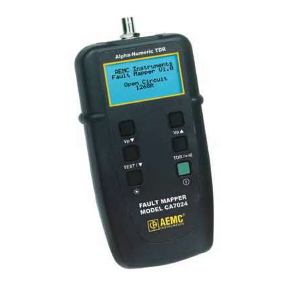
- Page 6 fault on the cable, given access to only one end. By incorporating Fast-edge Step TDR Technology, the Fault Mapper measures cable length and indicates the distance to open or short circuit faults, to a range The Fault Mapper indicates the cable length or fault distance and description alpha-numerically on a 128x64 Graphical LCD.
- Page 7 1. BNC input connector 2. Alpha-Numeric LCD 3. Vp (Velocity of Propagation) decrement button 4. Test /function select button 5. Backlight button 6. Vp (Velocity of Propagation) increment button 7. Mode select button (TDR or Tone Tracer)
- Page 8 Range @ Vp=70%: 6000 ft (2000m) Resolution (m): 0.1 m up to 100 m, then 1 m Resolution (ft): 0.1 ft up to 100 ft, then 1 ft Accuracy*: ±2% of Reading Minimum Cable Length: 12 ft (4m) Cable Library: Built-in Vp (Velocity of Propagation): Adjustable from 0 to 99% Output Pulse:...
- Page 9 to the far end of the cable under test, or to an intermediate fault and return. Based on the selected Vp and the measured travel time of the test pulse, the Fault Mapper calculates and displays distance. The Fault Mapper measures distances to faults and cable lengths to an accuracy of ±...
- Page 10 gation, and remaining battery capacity. Hold the button, then press the button to enter Set-up mode. Italiano Press the button to move the line selector (> Press the button to change the setting of the line selected. Press the button again to save changes and exit set-up mode. NOTE: current set-up parameters.
- Page 11 To program a custom library location, enter the Set-up mode (see § 4.4). Press the be at Edit Library. Press the button to enter the library programming mode. tion in the library. Custom Cable X = 50% Press the button to choose a cable location to program. Next, press the button enter the Choose Character mode.
- Page 12 Pressing Set-up mode. button. The Fault Mapper may also be used as a tone generator, to trace and the AEMC Tone Receiver/Cable Tracer Model TR03 (Cat. #2127.76) or...
- Page 13 Pressing the second. NOTE: The auto-off function is disabled in Tone Generator mode, so that the tone can be injected into a cable for an extended period See §4.11 for attaching a cable to the Fault Mapper WARNING: If the Fault Mapper is accidentally connected to a cable appear.
- Page 14 Velocity of Propagation (Vp) values are characteristic of each cable type and brand. The Vp is used to measure the length of a cable and to measure a fault location. The more accurate the Vp, the more accurate the measurement cable batch variations or for special cable applications.
- Page 15 Press the Cable Type Vp (%) A.I.W 10/4 A.I.W 16/3 Alarm Belden Alarm M/Core Belden 8102 Belden 9116 Belden 9933 CAT5 STP CAT5 UTP Cirtex 12/2 Coax Air Coax Air Space Coax Foam PE Coax Solid PE Coloniel 14/2 CW1308 Encore 10/3 Encore 12/3 Encore HHW-2...
- Page 16 If the cable to be tested is not listed in the library, or a different Vp is button, past the top of the library. NOTE: last selected Cable Library or Vp setting. This feature is useful in the type of cable.
- Page 17 cable to be tested. 3. Attach the Fault Mapper to one end of the cable to be tested. The cable attachment is via a BNC connector located at the top of the unit. For unterminated cables use the alligator clip attachment provided. Coaxial Cable: Connect the Black clip to the center wire and the Red clip to the shield/screen.
- Page 18 (see § 4.9) and attach to the cable to be tested as previously described in § 4.11. button. Assuming there are no opens or shorts in the cable, the length of the cable place. For lengths over 100 ft the decimal place is suppressed. If there is a short at the end of the cable or at some point along the cable,...
- Page 19 ® done other than by its service center or by an approved repair center. 1. Turn the instrument OFF. the polarities. 4. Reattach the battery compartment cover. Disconnect the instrument from any source of electricity. If the instrument is not used for a period of more than 60 days, it is recom- mended to remove the batteries and store them separately.
- Page 20 Service Center at one-year intervals For instrument repair and calibration: shipping container. Ship To: Chauvin Arnoux , Inc. d.b.a. AEMC Instruments ® ® 15 Faraday Drive Dover, NH 03820 USA Phone: (800) 945-2362 (Ext. 360) (603) 749-6434 (Ext.
- Page 21 -ranty is given by AEMC ® if the defect is related to service not performed by AEMC ® Instruments. For full and detailed warranty coverage, please read the Warranty Coverage Information, which is attached to the Warranty Registration Card (if enclosed) or is available at www.aemc.com. Please keep the Warranty Coverage Information with your records.
- Page 22 1.1 Comprobación de su pedido ...........22 1.2 Información del pedido ............22 ........22 2.1 Descripción ................23 2.2 Descripción del Panel frontal del Fault Mapper ......24 4.1 Principios de Funcionamiento ..........26 4.2 Precisión y Velocidad de Propagación (Vp) ......26 ................27 ............27 ..28 4.6 Retroiluminación ..............29 4.7 Generado de Tono ..............29...
- Page 23 1995. cuando repare el instrumento. ®...
- Page 24 Fault Mapper Modelo CA7024 .(Descontinuado)....Cat. #2127.80 (Descontinuado ya no está disponible para su compra). Incluye medidor, bolsa, BNC con clips de tipo cocodrilo, 4 x 1.5V AA bate- rías, manual del usuario y garantía del producto....Cat. #2127.76...
- Page 25 El Fault Mapper es un instrumento de mano, Alfa- Numérico, TDR, medidor la longitud en cables de potencia y de comunicación, o indicar la distancia del Mapper, mide longitudes de cables e indica la distancia donde esta abierto o hay un corto circuito, a una distancia de 6000 ft (2000m) en al menos 2 conductores.
- Page 26 1. Conector de entrada BNC 2. LCD Alfa numérico 3. Botón de decremento de Vp (Velocidad de Propagación) 4. Selector de función de prueba (Test) 5. Botón para la retroiluminacion 6. Botón para el incremento de VP (velocidad de Propagación) 7.
- Page 27 Rango a Vp=70%: 6000 ft (2000m) Resolución (m) : 0.1 m hasta 100 m, entonces 1 m Resolución (ft) : 0.1 ft hasta 100 ft, entonces 1 ft Precisión: ±2% en lectura Longitud mínima del cable: 12 ft (4m) Librería de Cables: Vp (Velocidad de propagación): Ajustable desde 0% a 99% Pulso de Salida:...
- Page 28 recorrer el cable, el Fault Mapper calcula y muestra la distancia. El Fault Mapper mide la distancia del cable o hasta el fallo con una preci- sión del ±2%. Esta precisión en la medida esta basada en un valor correcto de Vp siendo lo largo del cable.
- Page 29 El instrumento se enciende y se apaga con el interruptor verde situado en la parte baja del lateral derecho del panel frontal ( Cuando se enciende la unidad mostrara en la pantalla la versión del soft- Sujetar el botón , entonces presione el botón de Test para o en Metros.
- Page 30 para seleccionar Edit Library (Editar para entrar en el modo de pro- Presione los botones para programar. Presionar para entrar en el modo de Selección de Carácter. Presione los botones para mover la selección del cursor a la para entrar en el Después presione los botones puntero de selección.
- Page 31 para ir al vuelva a presionar para mover el cursor al ajuste VP. A continua- ción, presione para aumentar o disminuir el VP. por tercera botón La retroiluminación de la pantalla se enciende y se apaga con el botón.
- Page 32 Presionando el botón segundo. Nota: La función de auto apagado esta incapacitada en el modo de Gene- rador de Tono, de esta manera el tono puede ser introducido al cable por Vea la sección 4.11 para unir un cable al Fault Mapper tensión.
- Page 33 cada tipo de cable y fabricante. la medida. determinarlo para compensar las variaciones del cable, o para una aplica- ción especial del cable. Es muy sencillo: 1. Tome un cable como muestra con la medida exacta (ft o m) mayor de 60ft (20m). 2.
- Page 34 Presione los botones para moverse hacia arriba o hacia abajo Cables Vp (%) A.I.W 10/4 A.I.W 16/3 Alarm Belden Alarm M/Core Belden 8102 Belden 9116 Belden 9933 CAT5 STP CAT5 UTP Cirtex 12/2 Coax Air Coax Air Space Coax Foam PE Coax Solid PE Coloniel 14/2 CW1308...
- Page 35 , hasta pasar la 99%. Si desconoce el valor de Vp, vea el apartado 4.9. NOTA: Cuando apague el Fault Mapper, este recordara el ultimo esta haciendo diversas pruebas en un mismo tipo de cable.
- Page 36 de tipo cocodrilo. Cable Coaxial: Conecte la pinza Negra al hilo de en medio Rojo al blindaje o apantallado. Cable Apantallado: Conecte la pinza de color Negra al hilo contiguo al apantallado Par Trenzado: uno de los hilos del par. Cable Multiconductor:...
- Page 37 del cable (ver 4.9), y conecte el cable a comprobar de la forma descrita anteriormente (ver 4.11). largo del cable, se mostrara la distancia de donde se encuentra el fallo.
- Page 38 técnico o por un servicio acreditado. Desconecte el instrumento de cualquier cable o red de enlace. 1. Apague el instrumento. observando la polaridad. Desconecte el instrumento de cualquier fuente de electricidad.
- Page 39 Para reparación o calibración de instrumentos: CSA# por fuera del embalaje. ® Chauvin Arnoux , Inc. ® d.b.a. AEMC Instruments Tel: (603) 749-6434 (Ext. 360) Fax: (603) 742-2346 or (603) 749-6309 repair@aemc.com NOTA: Todos los clientes deberán obtener el CSA# antes de devolver el instrumento.
- Page 40 AEMC Instruments, no por el distribuidor al cual fue sido mal tratada o defectuosa por uso indebido, o por reparaciones no efec-tuadas por nuestro servicio técnico de AEMC Instruments. archivos. Que puede hacer AEMC: -darnos la Tarjeta de Registro.
- Page 42 1.1 Ao Receber o Produto ............42 ............42 ......42 ................43 ..........45 ............48 ......48 4.3 Iniciando .................49 ..............49 .......50 4.6 Backlight .................52 4.7 Gerador de Tom ..............52 ..53 4.9 Determinando e Medindo Valores da Vp ........53 4.10 Selecionando um Cabo na Biblioteca e Ajustando a Vp..54 4.10.1 Biblioteca de Cabos ............54 4.11 Conectando um Cabo ao Fault Mapper ........56 4.12 Medindo o Comprimento do Cabo ou a...
- Page 43 1:1995. em linhas telefônicas de acordo com o estipulado na norma EN61326-1. operador. mento.
- Page 44 Fault Mapper Modelo CA7024 ....... N de Catálogo #2127.80 Descontinuado, não está mais disponível para compra. Inclui o instrumento, bolsa de transporte, cabo BNC do tipo “pigtail” (“rabi- 1,5V, manual do usuário e cartão de garantia do produto. Receptor De Tom / Tracer Do Cabo TR03 ..N...
- Page 45 (curto ou aberto) bastando Por incorporar a Tecnologia TDR Fast-edge Step, o Fault Mapper Modelo CA7024 pode medir o comprimento de cabos e indicar a distância até onde ocorreu uma falha (curto ou aberto) numa faixa de até 2.000m O Modelo CA7024 exibe alfanumericamente o comprimento do cabo ou a (Vp).
- Page 46 Características: midades do cabo até o ponto onde ocorreu a falha numa faixa até 2.000m (6,000ft). distância até o ponto onde ocorreu a falha. amostra sob teste.
- Page 47 1. Conector de entrada tipo BNC 2. LCD alfanumérico Tom)
- Page 48 Faixa da Vp=70% 2.000m (6,000ft) Resolução (m) 0,1m para distâncias até 100m 1m para distâncias acima de 100m Resolução (ft) 0,1ft para distâncias até 100ft 1ft para distâncias acima de 100ft Precisão* ±2% do valor da leitura Comprimento Mínimo do Cabo 4m (12ft) Biblioteca de Cabos Interna Vp (Velocidade de Propagação)
- Page 49 Temperatura de Operação 0º a 40ºC (32ºF a 112ºF) Altitude Dimensões 165 x 90 x 37mm (6.5 x 3.5 x 1.5”) Peso Segurança IEC61010-1 EN60950 Índice de Proteção IP54 EN61326-1...
- Page 50 O Fault Mapper Modelo CA7024 mede as distâncias até falhas ou o com- seja homogênea ao longo de todo o comprimento do cabo.
- Page 51 verde Quando a unidade é ligada, ela exibe uma tela de abertura informando a (Espanhol), Português ou Italiano. na tela. para mudar o ajuste da linha selecio- nada.
- Page 52 diversos testes no mesmo tipo de cabo. até posicionar o seletor de linha (>) em Edit Library (Editar Biblioteca). biblioteca. Custom Cable X com Vp=50% ser programada. Em seguida, pressione para entrar no modo Choose Character (Selecionar Caractere).
- Page 53 cabo. direita respectivamente. sione para entrar no modo Edit Character (Editar Caractere). para para alterar o carac- tere. Quando o caracter desejado for selecionado, pressione o para novamente para mover o cursor para o VP ajuste. A seguir pressione o para aumentar ou diminuir o Vp.
- Page 54 bida: NOTA: rastreamento é feito.
- Page 55 Se o instrumento for acidentalmente conectado a um cabo que apresenta uma tensão maior que 10V, um som de alerta será emitido, o teste será cancelado e no display aparecerá uma mensagem de alerta como a indicada abaixo. mento do cabo. cada tipo e marca de cabo.
- Page 56 para movimentar-se para cima e para Cabos Vp (%) A.I.W 10/4 A.I.W 16/3 Alarm Belden Alarm M/Core Belden 8102 Belden 9116 Belden 9933 CAT5 STP CAT5 UTP Cirtex 12/2 Coax Air Coax Air Space Coax Foam PE Coax Solid PE Coloniel 14/2 CW1308 Encore 10/3...
- Page 57 até passar o topo da biblioteca. NOTA:...
- Page 58 pamento conectado ao cabo a ser testado. 3. Conecte o Fault Mapper a uma das extremidades do cabo a ser tes- tado. Cabo Coaxial: Cabo Blindado Par Trançado: Separe um dos pares e conecte os prendedores Cabo Multi-condutor:...
- Page 59 Vp do cabo (veja o § 4.9), e conecte o cabo a ser testado como des- crito anteriormente no § 4.11. uma casa decimal.
- Page 60 incidente ou mal funcionamento ocorrido após um reparo no instrumento Desconecte o instrumento de qualquer cabo ou terminação de rede. 1. Desligue o instrumento. 2. Desaperte os 2 parafusos e remova a tampa do compartimento da bateria. 3. Substitua as baterias por 4 baterias alcalinas tipo AA de 1,5V, obser- vando as polaridades.
- Page 61 Para conserto e calibração do instrumento: nhado e prontamente processado. Por favor, escreva claramente o CSA# na Chauvin Arnoux , Inc. d.b.a. AEMC Instruments ® ® Tel: (603) 749-6434 (Ext. 360) Fax: (603) 742-2346 or (603) 749-6309 repair@aemc.com NOTA: Todos os clientes precisam obter um CSA# antes de retornarem qualquer instrumento.
- Page 62 é oferecida pela AEMC ® Para obter informações detalhadas sobre a cobertura desta garantia, por favor, leia o Cartão de Cobertura de Garantia que encontra-se ane- xado ao Cartão de Registro de Garantia. Por favor, mantenha e guarde consigo o Cartão de Cobertura de Garantia.
- Page 64 08/24 99-MAN 100269 v14 Chauvin Arnoux , Inc. d.b.a. AEMC Instruments ® ®...
Need help?
Do you have a question about the CA7024 and is the answer not in the manual?
Questions and answers