Table of Contents
Advertisement
Quick Links
Download this manual
See also:
User Manual
Advertisement
Table of Contents

Related Manuals for AEMC 4500


Summary of Contents for AEMC 4500
- Page 1 4500 DIGITAL GROUND RESISTANCE TESTER E N G L I S H User Manual...
- Page 2 Owner’s Record The serial number for the Model 4500 is located on the front of the instru- ment. Please record this number and purchase date for your records. GROUND RESISTANCE TESTER MODEL 4500 CATALOG #: 450.100 SERIAL #: _______________________________________________ PURCHASE DATE: ________________________________________...
-
Page 3: Table Of Contents
Table of Contents 1. INTRODUCTION ..............3 1.1 International Electrical Symbols .............4 1.2 Receiving Your Shipment ...............4 1.3 Ordering Information ..............4 1.3.1 Accessories and Replacement Parts ........4 2. PRODUCT FEATURES ............6 2.1 Description ..................6 2.2 Detaching the Cover ..............7 2.3 Control Features ................8 3. - Page 4 4.7 Continuity Measurement ..............31 4.8 Soil Resistivity Measurements .............32 (4-Point) ........33 4.9 Soil Resistivity Measurement Procedure 4.10 Multiple Electrode System ............36 5. MAINTENANCE ..............38 5.1 Warning ..................38 5.2 Power Supply ................38 5.2.1 Testing Battery Voltage ............38 5.2.2 Average Operating Time ..........38 5.2.3 Recharging Built-In Battery ..........39 5.2.4 Power Supply from External Battery .......39 5.2.5...
-
Page 5: Introduction
• AEMC Instruments considers the use of rubber gloves ® to be an excellent safety practice even if the equipment is properly operated and correctly grounded. • Always inspect the instrument and leads prior to use. Replace any defective parts immediately. Digital Ground Resistance Tester Model 4500... -
Page 6: International Electrical Symbols
Save the damaged packing container to substantiate your claim. Ordering Information Ground Resistance Tester Model 4500 ....... Cat. #450.100 Includes AC power supply cord, 12V nickel-cadmium battery (installed), adhesive label (C1- P1-P2-C2), hex key, spare fuse, and user manual. - Page 7 Set of 2, T-shaped Auxiliary Ground Electrodes ....Cat. #100.335 Ground Tester Video/Workbook Set ........Cat. #2130.64 25Ω Calibration Checker ............. Cat. #2130.59 Tape Measure – AEMC 100 ft..........Cat. #2130.60 NEW: Order Accessories and Replacement Parts Directly Online Check our Storefront at www.aemc.com for availability Digital Ground Resistance Tester Model 4500...
-
Page 8: Product Features
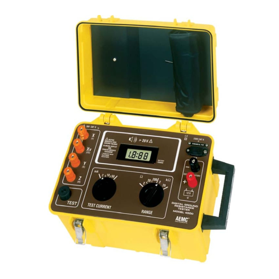
X and Y or X and Z when the ground leads are connected. The Model 4500 can be used to perform soil resistivity measurements with the four-point method by using the high 20kΩ range and is designed in a sturdy, dust and water-resistant carrying case with a detachable cover. -
Page 9: Detaching The Cover
To detach the cover from the case, apply downward pressure to the rear portion of the cover while gripping it firmly. To re-attach the cover, fit the hinges into the respective housings and apply strong rear-to-front pressure to the cover until it snaps into place. Unhinging Supporting Point Figure 2 Digital Ground Resistance Tester Model 4500... -
Page 10: Control Features
8. Low battery indicator 9. Display 10. Battery charge indicator 11. Supply voltage indicator 12. Jack for power supply cord 13. Connecting terminals for power supply from external battery (12V 14. Range selector switch 15. Test Current selector switch 16. Adhesive label (C-1, P-1, P-2, C-2) supplied with each instrument Digital Ground Resistance Tester Model 4500... -
Page 11: Specifications
Operating Frequency: 128Hz square wave Dielectric Test: 2000Vrms, 50/60Hz between four interconnected mea- suring terminals and any external metal ground between line input and measuring terminals on front panel. Power Supply: One built-in rechargeable 12V battery, or external 12V Battery Life: 4 hrs on 50mA test current (800 15-second measurements) 7 hrs on 2mA and 10mA test currents (1500 15-second measurements) Digital Ground Resistance Tester Model 4500... -
Page 12: Accuracy
± 2% ± 1ct of 10% to 100% 50mA of full scale 10mA 2kΩ 1Ω 50mA* 2mA* 10mA* 20kΩ 10Ω 50mA* No accuracy specification - do not use * See Table III for maximum auxiliary resistance Digital Ground Resistance Tester Model 4500... -
Page 13: Table Of Influencing Parameters
3. From 10% to 100% of measuring scale interval. It is necessary to add the following quantities to those indicated with Table 1: ± 10mΩ for 2Ω /2mA range ± 3mΩ for 2Ω /10mA range ± 1 count for other ranges Digital Ground Resistance Tester Model 4500... -
Page 14: Influence Of Stray Voltage
20 k Ω Current 50 mA Rx + Rz = 600Ω max 10 mA Rx + Rz = 4000Ω max 2 mA Rx + Rz = 20 kΩ max Do not use Table 3 * Even if auxiliary resistance of Rz = 0, the maximum reading is < 2000-counts on these three ranges (voltage limiting circuit at output terminals). Digital Ground Resistance Tester Model 4500... -
Page 15: Mechanical Specifications
Table 4 Mechanical Specifications Display: 2000-count, 7 segment LCD, .71" (3-1/2 digit) Connection: Via terminals (wires; forked lugs with min gap of 6mm) banana jacks with Ø 4mm Operating Temperature: 14° to 122°F (-10° to 50°C) Case: Heavy-duty plastic, with detachable cover and carrying handle Colors: Case - Safety yellow; Front Panel - Brown Dimensions: 15.75 x 10.2 x 9.8" (400 x 260 x 250mm) Weight: 14 lbs (6.5 kg) approximate Digital Ground Resistance Tester Model 4500... -
Page 16: Safety Specifications
Shock and vibration according to MIL-T-28800D class 3 Environmental: O-ring sealed faceplate against water and dust, sealed cover when closed; IEC529, DIN 0470-T1 EN 61010-1 +A2 (ed. 95) Double Insulation 30V, Cat. II for measurement 230V, Cat. II for battery charger 12V, Cat. II for auxiliary supply EN 61557 Electromagnetic Compatibility: Emmission and Immunity: IEC 61326-1 (ed. 98) Digital Ground Resistance Tester Model 4500... -
Page 17: Operation
Ground Rod and Clamp Contact Resistance Between Rod and Soil Concentric Shells of Earth Figure 4 Digital Ground Resistance Tester Model 4500... - Page 18 The equations for systems of electrodes are very complex and often expressed only as approximations. The most commonly used formula for single ground electrode systems, developed by Professor H. R. Dwight of the Massachusetts Institute of Technology, follows: ρ {(In 4L) -1} R = 2πL R = resistance in ohms of the ground rod to the earth (or soil) L = grounding electrode length r = grounding electrode radius ρ = average resistivity in ohms-cm Digital Ground Resistance Tester Model 4500...
-
Page 19: Effect Of Electrode Size/Depth On Resistance
In general, doubling the rod length reduces the resistance by an additional 40%. 1" dia. 1/2" dia. 35 40 Driven Depth in Feet Ground Resistance Versus Ground Rod Depth Figure 6 Digital Ground Resistance Tester Model 4500... -
Page 20: Effects Of Soil Resistivity On Electrode Resistance
4.1.3 Factors Affecting Soil Resistivity Two samples of soil, when thoroughly dried, may become in fact very good insulators, having a resistivity in excess of 109 ohm-centimeters. The resistivity of the soil sample is seen to change quite rapidly until approxi- mately twenty percent or greater moisture content is reached. Digital Ground Resistance Tester Model 4500... - Page 21 Such varia- tions are shown in Figure 7 below. Since both temperature and moisture content become more stable at greater distances below the surface of the Digital Ground Resistance Tester Model 4500...
- Page 22 The Effect of Salt* Content on the Resistivity of Soil (sandy loam, moisture content, 15% by weight, temperature 17˚C) Added Salt Resistivity % by weight of moisture (Ohm-centimeters) 10,700 1,800 Table 8 Digital Ground Resistance Tester Model 4500...
-
Page 23: Effect Of Ground Electrode Depth On Resistance
10,000 ohm-centimeters, a 5/8" OD rod must be driven 20 feet. NOTE that the values indicated on the Nomograph are based on the assumption that the soil is homogeneous and, therefore, has uniform resistivity (Figure 8). The Nomograph value is an approximation. Digital Ground Resistance Tester Model 4500... -
Page 24: Ground Resistance Values
25Ω or less to ground shall be augmented by one additional electrode of any of the types specified by 250.52 (A)(4) through (A)(8). Where multiple rod, pipe or plate electrodes are installed to meet the requirements of the section, they shall not be less than 6 feet apart. Digital Ground Resistance Tester Model 4500... - Page 25 Ground rods, of course, will be required in high voltage transmission lines, where maximum resistance of 15Ω is recommended; and in distribution lines, where maximum resistance of 25Ω is preferred. All electrical sys- tems constructed in accordance with the National Electrical Code , should ® not exceed 25Ω. Digital Ground Resistance Tester Model 4500...
-
Page 26: Ground Resistance Testing Principle
It is not necessary to carry out all the measurements when using a ground tester. The ground tester will measure directly by generating its own cur- rent and displaying the resistance of the ground electrode. Digital Ground Resistance Tester Model 4500... -
Page 27: Position Of Auxiliary Electrodes In Measurements
The goal in precisely measuring the resistance to ground is to place the auxiliary current electrode Z far enough from the ground electrode under test so that the auxiliary potential electrode Y will be outside of the effec- tive resistance areas of both the ground electrode and the auxiliary current electrode. The best way to find out if the auxiliary potential rod Y is outside the effective resistance areas is to move it between X and Z and to take a reading at each location. If the auxiliary potential rod Y is in an effective resistance area (or in both if they overlap), by displacing it, the readings taken will vary noticeably in value. Under these conditions, no exact value for the resistance to ground may be determined. Digital Ground Resistance Tester Model 4500... -
Page 28: Measuring Resistance Of Ground Electrodes
This method applies only when all three electrodes are in a straight line and the ground is a single electrode, pipe, or plate, etc., as in Figure 12. Digital Ground Resistance Tester Model 4500... - Page 29 Now consider Figure 14, where the X and Z electrodes are sufficiently spaced so that the areas of effective resistance do not overlap. If we plot the resistance, measured we find that the measurements level off when Y is placed at 62% of the distance from X to Z, and that the readings on Digital Ground Resistance Tester Model 4500...
-
Page 30: Auxiliary Electrode Spacing
50 ft. 80 ft. 10 ft. 55 ft. 88 ft. 12 ft. 60 ft. 96 ft. 18 ft. 71 ft. 115 ft. 20 ft. 74 ft. 120 ft. 30 ft. 86 ft. 140 ft. Digital Ground Resistance Tester Model 4500... -
Page 31: Ground Resistance Measurement Procedures
Ranges 2Ω 20Ω 200Ω 2000Ω 20kΩ Resolution 1mΩ 10mΩ 0.1mΩ 1Ω 10Ω Recommended 10mA or 2mA or 2mA or 2mA, 10mA, Current Ranges 50mA or 50mA 10mA 10mA Digital Ground Resistance Tester Model 4500... -
Page 32: Over-Range Indication
This method should not be used as a stan- dard procedure, but rather as a backup in tight areas. See Figure 16. Digital Ground Resistance Tester Model 4500... -
Page 33: Continuity Measurement
TEST CURRENT RANGE Butt plate Figure 16 Continuity Measurement After the shorting strip has been properly positioned between X and Xv (C1, P1), connect the Y (P2) and Z (C2) terminals together as well. Continuity measurement is made with two leads, one from X-Xv, the other from Y-Z (P2, C2); push the “TEST” button to measure. Digital Ground Resistance Tester Model 4500... -
Page 34: Soil Resistivity Measurements
The 2-point method is simply the resistance measured between two points. For most applications, the most accurate method is the 4- point method, which is used in the Model 4500 Ground Tester. The 4- point method, as the name implies, requires the insertion of four equally spaced, and in-line, electrodes into the test area. -
Page 35: Soil Resistivity Measurement Procedure (4-Point)
Given a sizeable tract of land in which to determine the optimum soil resis- tivity, some intuition is in order. Assuming that the objective is low resis- tivity, preference should be given to an area containing moist loam as opposed to a dry sandy area. Consideration must also be given to the depth at which resistivity is required. Digital Ground Resistance Tester Model 4500... - Page 36 “A” between the electrodes must then be equivalent to the depth at which average resistivity is to be determined (15 ft, or 450cm). Using the more simplified Wenner formula (ρ = 2π AR), the electrode depth must then be 1/20th of the electrode spacing or 8-7/8" (22.5cm). Lay out the electrodes in a grid pattern (Figure 20) and connect to the Model 4500 as shown in Figure 19. Proceed as follows: • Remove the shorting strip between X and Xv • Connect all four auxiliary rods...
- Page 37 For example, if the reading is R = 15, ρ (resistivity) = 2π x R x A A (distance between electrodes) = 450cm ρ = 6.28 x 15 x 450 = 42,390 Ω-cm 20 200 2 10 50 DIGITAL GROUND RESISTANCE TESTER MODEL 4500 TEST TEST CURRENT RANGE Figure 19 Figure 20 Digital Ground Resistance Tester Model 4500...
-
Page 38: Multiple Electrode System
In multiple electrode systems, the 62% method electrode spacing may no longer be applied directly. The distance of the auxiliary electrodes is now based on the maximum grid distance (e.g. in a square, the diagonal; in a line, the total length. For example, a square having a side of 20 ft will have a diagonal of approximately 28 ft). DIAGONAL Figure 21 Digital Ground Resistance Tester Model 4500... - Page 39 310 ft 500 ft 120 ft 341 ft 550 ft 140 ft 372 ft 600 ft 160 ft 390 ft 630 ft 180 ft 434 ft 700 ft 200 ft 453 ft 730 ft Digital Ground Resistance Tester Model 4500...
-
Page 40: Maintenance
If the colon lights up, the battery has lost power. Thereafter, the available operating time remaining is approximately 100 15-second measurements. When this situation arises, recharge the battery at once or obtain power from an external battery (see the following paragraphs). Digital Ground Resistance Tester Model 4500... -
Page 41: Recharging Built-In Battery
Ribbon Cable • Remove the wing nuts, the spacers, and the Case protective cover to gain Fastening Screws access to the two 12V DC battery (See Figure Figure 22 23). Digital Ground Resistance Tester Model 4500... -
Page 42: Changing The Supply Voltage (110/220V Ac )
Power Supply Board Switch (110V AC/220V AC) 110V 220V 3.15 A 12 V Supply Fuse 12 V DC Figure 24 5.2.6 Changing the Supply Voltage (110/220V • Open up the Model 4500. Position the selector switch on the power supply board (See Figure 24). • Set the plate (“11” in Figure 3) which indicates “220V AC” on one side and “110V AC” on the other, to the selected voltage. • Reassemble the Model 4500. Digital Ground Resistance Tester Model 4500... -
Page 43: Replacing The Supply Fuse
To replace this fuse: • Remove the six hex screws from the bottom of the case (see Figure 22), and lift the chassis from the case housing. • Replace the fuse (Figure 24) and reassemble the instrument. 5.2.8 Replacing the Safety Fuse An internal fuse which provides protection for up to 500V AC is used to protect the instrument against voltages into the test leads. To replace this fuse: • Remove the six hex screws from the bottom of the case (see Figure 22), and lift the chassis from the case housing. • Turn the chassis over. • Replace the fuse (Figure 25) and reassemble the instrument. Digital Ground Resistance Tester Model 4500... -
Page 44: Cleaning
Replacement Fuse Columns Chassis Installed Safety Fuse Figure 25 Cleaning Disconnect the instrument from any source of electricity. • Use a soft cloth lightly dampened with soapy water. • Rinse with a damp cloth and then dry with a dry cloth. • Do not use alcohol, solvents or hydrocarbons. Storage If the instrument is not used for an extended time period, the battery should be recharged regularly. Three-month intervals are recommended. Digital Ground Resistance Tester Model 4500... -
Page 45: Repair And Calibration
If you are experiencing any technical problems, or require any assistance with the proper operation or application of your instrument, please call, fax or e-mail our technical support team: Contact: Chauvin Arnoux , Inc. d.b.a. AEMC Instruments ® ® Phone: (800) 945-2362 (Ext. 351) (603) 749-6434 (Ext. 351) Fax: (603) 742-2346 E-mail: techsupport@aemc.com Digital Ground Resistance Tester Model 4500... -
Page 46: Limited Warranty
Limited Warranty The Model 4500 is warranted to the owner for a period of 2 year from the date of original purchase against defects in manufacture. This limited warranty is given by AEMC Instruments, not by the distributor from whom it was pur- ®... - Page 48 02/18 99-MAN 100033 v12 Chauvin Arnoux , Inc. d.b.a. AEMC Instruments ® ® 15 Faraday Drive • Dover, NH 03820 USA • Phone: (603) 749-6434 • Fax: (603) 742-2346 www.aemc.com...
Need help?
Do you have a question about the 4500 and is the answer not in the manual?
Questions and answers