
Related Manuals for AEMC 4500


Summary of Contents for AEMC 4500
- Page 1 Digital Ground Resistance Tester Model 4500 USER MANUAL Chauvin Arnoux, Inc. d.b.a. AEMC ® Instruments • 99 Chauncy St. • Boston, MA 02111 USA 99-MAN-100033 Rev 02 02/98...
- Page 2 Digital Ground Resistance Tester Model 4500 USER MANUAL 50/60/400 Hz_110V BEEPER INDICATES HIGH GROUND VOLTAGE BLINKING DISPLAY POINTER INDICATE EXCESSIVE BATTERY - TRANSIENT NOISE - ELECTRODE CHARGE RESISTANCE EXTERNAL BATTERY Ω kΩ 20 200 2 10 50 12 V DIGITAL GROUND...
- Page 3 Owner’s Record The serial number for the Model 4500 is located on the outside of the instrument. Please record this number and purchase date for your records. DIGITAL GROUND RESISTANCE TESTER MODEL 4500 CATALOG #: SERIAL #: PURCHASE DATE: DISTRIBUTOR:...
-
Page 4: Table Of Contents
Table of Contents Receiving Your Shipment ....... . 2 Packaging ..........2 Warning . -
Page 5: Receiving Your Shipment
Save the damaged packing container to substantiate your claim. Packaging The Digital Ground Tester Model 4500 (Cat. #450.100) is shipped with power cord, 12 V nickel-cadmium battery, adhesive label (C1-P1-P2-C2), hex key, spare fuse, and user manual. The battery is set into the instru- ment when shipped. -
Page 6: Description
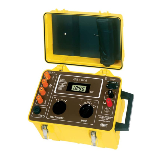
Description The Digital Ground Resistance Tester Model 4500 is a rugged, easy-to- use tester which is specifically designed for measuring very low resis- tance on large grounding systems (ground grids, ground mats), even under difficult conditions such as high stray currents or excessive aux- iliary electrode resistance. -
Page 7: Detaching The Cover
#100.525), Cat. #100.526 Set of one rechargeable replacement battery (12 V DC), Cat. #2960.10 Fuse, set of three 3.15 A (250 V) for Model 4500, Cat. #100.357 Set of two, T-shaped ground rods, Cat. #100.335 Fuse, set of five 0.1 A for Models 4500/4600, Cat. #2970.12... -
Page 8: Control And Connector Identification
8. Connecting terminals for 14. Supply voltage indicator power supply from external 15. Ground resistance battery (12 V DC) measurement strip 9. Display 16. Adhesive label 10. Battery charge indicator (C-1, P-1, P-2, C-2 option) Digital Ground Resistance Tester Model 4500... -
Page 9: Specifications
128 Hz square wave Dielectric Test: 2000 V rms, 50/60 Hz between four interconnected measuring terminals and any external metal ground 2000 V rms, 50/60 Hz between line input and measuring terminals on front panel Digital Ground Resistance Tester Model 4500... - Page 10 2 mA 10 mA 2 kΩ 1Ω 50 mA* 2 mA* 10 mA* 20 kΩ 10Ω 50 mA* No accuracy specification - do not use * See Table III for maximum auxiliary resistance Digital Ground Resistance Tester Model 4500...
- Page 11 3. From 10% to 100% of measuring scale interval. It is necessary to add the following quantities to those indicated with Table I: ± 10 mΩ for 2Ω/2 mA range ± 3 mΩ for 2Ω/10 mA range ± 1 count for other ranges Digital Ground Resistance Tester Model 4500...
- Page 12 Rx + Rz = 20 k Table III Do not use * Even if auxiliary resistance of Rz = 0, the maximum reading is < 2000 counts on these three ranges (voltage limiting circuit at output terminals). Digital Ground Resistance Tester Model 4500...
- Page 13 Typical Operating Time: 4 h on 50 mA test current 7 h on 10 mA and 2 mA test currents Charging Time: 14 hours typical Charging Supply Voltage: Internally selectable 110/220 V, 45 to 450 Hz Digital Ground Resistance Tester Model 4500...
-
Page 14: Power Supply
If the colon does not light, the batteries are charged. Average Operating Time: • 4 hours on 50 mA test current (800 15-second measurements) • 7 hours on 2 mA and 10 mA test currents (1500 15-second measurements) Digital Ground Resistance Tester Model 4500... - Page 15 (“8” in Figure 3). Be sure to observe the proper polarities. The external battery does not charge the internal battery. Note that it is not necessary to remove the battery supplied with the instrument when using an external battery or supply. Digital Ground Resistance Tester Model 4500...
- Page 16 Wing Nuts Wing Nuts Stress Relief Plate Stress Relief Plate 12 V DC 12 V DC Lengthwise Lengthwise Locking Screws Locking Screws Shock-Absorbing Layer Power Supply Board Power Supply Board Shock-Absorbing Layer Figure 5 Digital Ground Resistance Tester Model 4500...
- Page 17 Figure 6 Changing the Supply Voltage (110/220 V AC) • Open up the Model 4500. Position the selector switch on the power supply board (See figure 6). • Set the plate (“14” in Figure 3, p. 5) which indicates “220 V Ac” on one side and “110 V Ac”...
- Page 18 4), and lift the chassis from the case housing. • Turn the chassis over. • Replace the fuse (Figure 7) and reassemble the instrument. Replacement Fuse Replacement Fuse Columns Columns Chassis Chassis Installed Safety Fuse Installed Safety Fuse Figure 7 Digital Ground Resistance Tester Model 4500...
-
Page 19: Grounding Electrode Resistance
Ground Rod Ground Rod and Clamp and Clamp Contact Contact Resistance Resistance Between Rod Between Rod and soil and Soil Concentric Concentric Shells of Shells of Earth Earth Figure 8 Digital Ground Resistance Tester Model 4500... - Page 20 {(ln 4L) -1} 2 π L R = resistance in ohms of the ground rod to the earth (or soil) L = grounding electrode length r = grounding electrode radius ρ = average resistivity in ohms-cm Digital Ground Resistance Tester Model 4500...
- Page 21 In general, doubling the rod length reduces the resistance by an additional 40% (Figure 10). 1" dia. 1/2" dia. 35 40 Figure 10 Driven Depth in Feet Ground Resistance Versus Ground Rod Depth Digital Ground Resistance Tester Model 4500...
- Page 22 Ashes, cinders, brine, waste 2,370 7,000 Clay, shale, gumbo, loam 4,060 16,300 Same, with varying proportions 1,020 15,800 135,000 of sand and gravel Gravel, sand, stones with 59,000 94,000 458,000 little clay or loam Figure 11 Digital Ground Resistance Tester Model 4500...
- Page 23 15.2% moisture, with temperature changes from 20 ° to -15 °C. In this temper- ature range the resistivity is seen to vary from 7200 to 330,000 ohm- centimeters. Digital Ground Resistance Tester Model 4500...
- Page 24 Seasonal variation of earth resistance with an electrode of 3/4 inch pipe in rather stony clay soil. Depth of electrode in earth is 3 ft for Curve 1, and 10 ft for Curve 2. Digital Ground Resistance Tester Model 4500...
- Page 25 The Effect of Salt* Content on the Resistivity of Soil (Sandy loam, Moisture content, 15% by weight. Temperature, 17°C) Added Salt Resistivity % by weight of moisture (Ohm-centimeters) 10,700 1,800 Figure 15 Digital Ground Resistance Tester Model 4500...
- Page 26 20 feet. Note that the values indicated on the Nomograph are based on the assumption that the soil is homogeneous and, therefore, has uniform resistivity (Figure 17). The Nomograph value is an approx- imation. Digital Ground Resistance Tester Model 4500...
- Page 27 D scale. 3. Lay straightedge on R and P scale, and allow to intersect 6. Point on D scale will be rod with K scale. depth required for resistance on R scale. Digital Ground Resistance Tester Model 4500...
-
Page 28: Ground Resistance Values
NEC®. When these situations develop, several methods of lowering the ground resistance can be employed. These include parallel rod sys- tems, deep driven rod systems utilizing sectional rods and chemical Digital Ground Resistance Tester Model 4500... - Page 29 AEMC ® Instruments has also recently intro- duced a clamp-on ground resistance tester. Note: The National Electrical Code ® and NEC ® are registered trade- marks of the National Fire Protection Association. Digital Ground Resistance Tester Model 4500...
-
Page 30: Ground Resistance Testing Principle (Fall-Of-Potential - 3-Point Measurement)
Ground Auxiliary Current GROUND AUXILIARY AUXILIARY Electrode Potential ELECTRODE POTENTIAL CURRENT Electrode Under Test Electrode UNDER TEST ELECTRODE ELECTRODE Earth EARTH Figure 18 (Note: Terminals X and Xv are shorted together in three-point measurement.) Digital Ground Resistance Tester Model 4500... - Page 31 X. The readings should be plotted to ensure that they lie in a “plateau” region as shown in Figure 20. Digital Ground Resistance Tester Model 4500...
-
Page 32: Measuring Resistance Of Ground Electrodes (62% Method)
Figure 21. 20 200 2 10 50 Ground TEST TEST CURRENT RANGE Ground Strip Strip Z Electrode Y Electrode Z Electrode Y Electrode Alligator Clips Alligator Clips Ground Rod Ground Rod Figure 21 Digital Ground Resistance Tester Model 4500... - Page 33 Y setting are most likely to be within the estab- lished tolerance band. This tolerance band is defined by the user and expressed as a percent of the initial reading: ± 2%, ± 5%, ± 10%, etc. Digital Ground Resistance Tester Model 4500...
- Page 34 50 ft. 80 ft. 10 ft. 55 ft. 88 ft. 12 ft. 60 ft. 96 ft. 18 ft. 71 ft. 115 ft. 20 ft. 74 ft. 120 ft. 30 ft. 86 ft. 140 ft. Digital Ground Resistance Tester Model 4500...
-
Page 35: Ground Resistance Measurement Procedure (3-Point)
20Ω 200Ω 2000Ω 20 kΩ Resolution 1 mΩ 10 mΩ 0.1Ω 1Ω 10Ω Recommended 10 mA 2 mA 2 mA 2 mA, 10mA, current ranges or 50 mA 50 mA 10 mA 10 mA Digital Ground Resistance Tester Model 4500... - Page 36 EXTERNAL BATTERY Ω kΩ 20 200 2 10 50 12 V DIGITAL GROUND RESISTANCE TESTER MODEL 4500 TEST TEST CURRENT RANGE AEMC I N S T R U M E N T S Figure 25 Digital Ground Resistance Tester Model 4500...
-
Page 37: 2-Point Measurement (Simplified Measurement)
Auxiliary Rod Auxiliary rod (Y-Z shorted) (Y-Z shorted) Utility pole Utility Ground Level Pole Ground level 20 200 2 10 50 Ground rod Ground Rod TEST TEST CURRENT RANGE Butt Plate Butt plate Figure 26 Digital Ground Resistance Tester Model 4500... -
Page 38: Continuity Measurement
Continuity measurement is made with two leads, one from X-Xv, the other from Y-Z (P2, C2); push the “TEST” button to measure. 20 200 2 10 50 TEST TEST CURRENT RANGE Figure 27 Digital Ground Resistance Tester Model 4500... -
Page 39: Soil Resistivity Measurements
The 2-point method is simply the resistance measured between two points. For most applications, the most accurate method is the 4-point method, which is used in the Model 4500 Ground Tester. The 4-point method, as the name implies, requires the insertion of four equally spaced, and in-line, electrodes into the test area. -
Page 40: Soil Resistivity Measurement Procedure (4-Point)
• Arrange the electrodes in a straight line. Be sure that distances between electrodes are identical: e.g., 3 meters between each elec- trode. (Consult Figure 28.) • The distance between poles is proportional to the average depth of the soil sample you wish to make. Digital Ground Resistance Tester Model 4500... - Page 41 (15 ft., or 450 cm). Using the more simplified Wenner formula (ρ = 2π AR), the electrode depth must then be 1/20th of the electrode spacing or 8-7/8" (22.5 cm). Digital Ground Resistance Tester Model 4500...
- Page 42 Lay out the electrodes in a grid pattern (Figure 30 below) and connect to the Model 4500 as shown in Figure 29. Proceed as follows: • Remove the shorting strip between X and Xv • Connect all four auxiliary rods For example, if the reading is R = 15, ρ...
-
Page 43: Multiple Electrode System
(i.e., in a square, the diago- nal; in a line, the total length. For example, a square having a side of 20 ft will have a diagonal of approximately 28 ft). DIAGONAL Figure 31 Digital Ground Resistance Tester Model 4500... - Page 44 500 ft 120 ft 341 ft 550 ft 140 ft 372 ft 600 ft 160 ft 390 ft 630 ft 180 ft 434 ft 700 ft 200 ft 453 ft 730 ft Figure 32 Digital Ground Resistance Tester Model 4500...
-
Page 45: Repair And Calibration
Repair and Calibration To guarantee that your instrument complies with the factory specifica- tions, we recommend that the Model 4500 be submitted to our factory service center at one-year intervals for recalibration, or as required by other standards. For instrument repair and/or calibration, please call our factory, toll-free, at (800) 945-AEMC (800-945-2362): CHAUVIN ARNOUX, Inc. -
Page 46: Technical And Sales Assistance
CHAUVIN ARNOUX, Inc. d.b.a. AEMC ® Instruments 99 Chauncy St. Boston, MA 02111 USA Tel: (800) 343-1391 (617) 451-0227 Fax: (617) 423-2952 www.aemc.com Digital Ground Resistance Tester Model 4500... - Page 47 We acknowledge and thank the ITT Blackburn Company for their per- mission to reprint numerous charts and graphs found in their Data folder 7303. This highly recommended and valuable Data folder is avail- able upon request from ITT Blackburn Company. Digital Ground Resistance Tester Model 4500...
- Page 48 Digital Ground Resistance Tester Model 4500...
-
Page 49: Limited Warranty
Instruments Will Do: If a malfunction occurs within the 1 ® year period, you may return the Digital Ground Resistance Tester Model 4500 to us for repair or replacement free of charge, provided we have your REGISTRATION CARD on file. AEMC ®...
Need help?
Do you have a question about the 4500 and is the answer not in the manual?
Questions and answers