Table of Contents
Advertisement
Quick Links
Advertisement
Table of Contents

Related Manuals for HELI gleen G Series


Summary of Contents for HELI gleen G Series
- Page 2 FOREWORD G series 1-2.5t lithium battery counterbalanced forklift truck is designed on the base of G series 1-2.5t battery counterbalanced forklift truck combined with lithium battery manage system. The truck has characters of environment friendliness, maintenance free, long service life, high efficient, energy saving, safety and it is suitable for low temperature.
-
Page 3: Table Of Contents
CONTENTS I. Safety Rules for Opeartion and Daily Maintenance of Forklift Truck ....... 1 II. Main Specifications of Forklift Truck ............... 6 III. Construction, Priciple, Adjustment and Maintenance of Forklift Truck ....9 1. Transmission System ..................9 2. Brake System ....................13 3. -
Page 4: Safety Rules For Opeartion And Daily Maintenance Of Forklift Truck
Ι. Safety Rules for Operation and Daily Maintenance of Forklift Truck It is important that driver and manager for forklift trucks remember the principle of the “first safety” and ensure the safety operation as the description in 《OPERATION AND SERVICE MANUAL》&《OPERATION MANUAL》. 1. - Page 5 (6) Complete the provisions before starting. (7) Release the parking lever. (8) Make trying operation of the mast for lifting, lowing and Fwd/Bwd tilting and the truck for steering and braking. 4. Operation of Forklift Truck (1) Only trained and authorized operator shall be permitted to operate the truck. (2) Wear all the safety guards, such as shoes, helmet, clothing and gloves while operating the truck.
- Page 6 (10) Never permit anyone to stand or walk under upraised forks. (11) Don’t operate truck and attachment of it at any position out of the drive seat. (12) On the high lift forklift truck, when the lift high more than 3m, it is noted that the goods on it should not fall down or the protection measures must be taken if necessary.
- Page 7 The clearance between the front floor and the pedal should be bigger than 20mm; d) Check parking brake. The unladen truck can park on the 15% grade ramp, when the parking lever is pulled to the bottom; e) Check instruments, lighting, switches and wiring to see if they work normally or not.
- Page 8 (3) The table of lubrication system...
-
Page 9: Main Specifications Of Forklift Truck
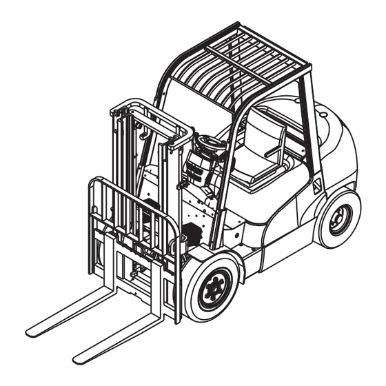
Ⅱ. Main Specifications of Forklift Truck Enternal view of forklift trucks... - Page 10 Main Specifications CPD10 CPD15 CPD18 Model Unit GC1Li GC1Li GC1Li /GD1Li /GD1Li /GD1Li Rated capacity 1000 1500 1750 Load center Lifting height 3000 Free lifting height ° Mast tilt angle (fwd/bwd) (K/T) 32× 100× 770 35× 100× 920 Fork size (L×...
- Page 11 Main Specifications CPD20 CPD25 Model Unit GC1Li /GD1Li GC1Li/GD1Li Rated capacity 2000 2500 Load center Lifting height 3000 Free lifting height Mast tilt angle (fwd/bwd) (K/T) ° 40× 122× 920 40× 122× 1070 Fork size (L× S× E) Wheelbase 1550 Tread (front/rear) (B1/B2) 960/950...
-
Page 12: Construction, Priciple, Adjustment And Maintenance Of Forklift Truck
Ⅲ. Construction, Principle, Adjustment and Maintenance of Forklift Trucks 1. Transmission System 1.1 General description The transmission system consists of differential assembly and gearbox & axle assembly. With direct connection of the drive gear and the drive motor, the travel speed of the truck can be changed with the speed of the motor, and the travel direction can be changed with the rotation direction of the motor. - Page 13 1.3 Gearbox & axle assembly The gearbox & axle assembly mainly consists of the housing, differential, half shaft, wheel hubs, brake and the wheels. It is installed in the front of the frame. The housing is an fission cast. The tyre with the rim is fixed to the hub with bolts and nuts.
- Page 14 (28) Washer 75 (29) Nut M75× 2 (30) Cone nut (31) Bolt M18× 1.5 (32) Brake assembly (L) Note: the bolts (9)(18)(24) should be applied with GY-340 adhesive; the o-ring shown in (11) used on 1-1.8t truck is 75× 5.3 and other trucks are 75× 5.3. Tightening torque:265-399N.m A is full of grease 50% Tightening torque:210-230N.m...
- Page 15 1.4 Assembly of wheel hub (1) Fill the chamber of wheel hub with lubricating grease about 100cc, and then fit the hub on the housing. (2) Screw down the hub nut to a torque of Adjust nut Locking plate 1kg.m, then loosen it for 1/2 turn. Locking nut Fig.
-
Page 16: Brake System
2. Brake System 2.1 General description The brake system is the front two-wheel braking type consisting of brake pedal, master cylinder and service brakes. 2.1.1 Brake pedal The structure of the brake pedal is shown in Fig. 2-1. The brake pedal is mounted on the transmission through bracket. - Page 17 rod pushes the piston forward. The brake fluid in the cylinder flows back to the reserve tank through the return port until the primary cup blocks up the return port. After the primary cup passes through the return port, the brake fluid in the cylinder is pressurized and opens the check valve, flowing through the brake pipeline to the sub cylinder.
- Page 18 2.1.3 Service brake The service brake is of double brake shoe type which is fitted to the each end of the gearbox & axle assembly. The service brake is made up of two brake shoe, sub cylinder and adjuster. The brake shoe, one end of it being connected to the anchor pin and the other to the adjuster, is stressed on backing plate by the spring and spring pull rod.
- Page 19 (2) Parking brake The parking brake is built in the service brake which is made up of push rod and pull rod. The pull rod is mounted to the primary shoe side by pin. The move of the pull rod is transmitted to the secondary shoe side through push rod.
- Page 20 travel. ▲Operation of the clearance self-adjuster When brake during travelling backward, the secondary brake shoe contact with main brake shoe and rotate together. Then the pulling rod turn right with point A as pivot and thus B point is raised up. See figure 2-6. When brake is released, the pulling rod turn left under the spring action and thus B point lowers.
- Page 21 Fig. 2-8 Brake assembly (1) Braking cable ass’y (2) Washer 8 (3) Bolt M8× 20 (4) Ratchet pawl (5) Pin roll (6) Torsional spring (7) Parking push rod (8) Spring (9) Rear brake shoe with friction plate (10) Spring pull rod (11) Return spring for brake shoe (12) Guide pad (13) Guide plate...
- Page 22 slope and ground. Brake force adjustment: When you turns the adjuster clockwise, the force increases, otherwise, when you turns the adjuster counter clockwise, the force decreases. (See Fig. 2-9) Pull force: 20 to 30kg. Note: Adjuster is inside the cover. Cover need to be disassembled before adjusting.
- Page 23 2.2.1 Service brake disassembly (1) Remove the support pin, adjusting lever, adjusting device and spring of secondary shoe. (See Fig. 2-10) Fig. 2-10 (2) Remove two shoes return springs. (See Fig.2-11) Fig. 2-11 (3) Remove the hold-down springs. (See Fig. 2-12) Fig.
- Page 24 (5) Remove the brake line from the brake cylinder. Remove brake cylinder mounting bolts and detach the brake cylinder from the backing plate. (See Fig. 2-14) Fig. 2-14 (6) Remove the E-retainer for securing the parking brake cable to the backing plate. Remove the backing plate mounting bolts and detach the backing plate from the axle.
- Page 25 (1) Check the operating cylinder inner surface and the piston periphery surface for rusting. Then, measure the clearance between the piston and cylinder. (See Fig.2-17) Fig. 2-17 Standard: 0.03-0.10mm Maximum clearance: 0.15mm (2) Visually check the piston cup for damage or deformation. If unsatisfactory, replace with new one.
- Page 26 2.2.3 Service brake reassembly (1) Apply brake fluid to the piston and the piston cup, and reinstall the spring, cup, the piston and the dust cover in this order. (2) Install the operating cylinder on the backing plate. (3) Install the backing plate on the front axle. (4) Apply heat-resisting grease on the points indicated in Fig.
- Page 27 (8) Install the shoe guide plate on the anchor pin, and install the shoe return spring. Install the main shoe first and then secondary shoe. (See Fig. 2-22) Fig. 2-22 (9) Install the adjuster, adjuster spring, push rod and its return spring. Pay attention to the following points: a) Adjuster thread direction and its mounting direction.
- Page 28 adjusting level with your finger along the arrow marks to turn the adjuster gear. When removing off your finger, the adjusting lever should return to its original position without rotation of the adjuster gear. Note: Even if the adjuster gear turn back along the adjusting lever motion when removing your finger, the adjuster will still operate normally after it is built in the machine.
- Page 29 (2) Adjust the stopper bolt and the height of the pedal. (See Fig. 2-26) (3) Press the brake pedal. Pull the push rod out until its front end comes into contact with the master cylinder piston. (4) Tighten the push rod locking nut. Pedal height Brake switch Pedal limit...
- Page 30 2.2.6 Service brake troubleshooting (See Table 5) Table 5 Problem Possible cause Remedy 1) Fluid leaks from brake system. Repair 2)Poor adjustment of brake shoe clearance. Adjust the adjuster 3)Brake overheating. Check for dragging 4)Poor contact between the brake drum and Readjust Poor braking friction piece.
-
Page 31: Steering System
3. Steering System 3.1 General Description The function of steering system of forklift is to change the driving direction of the forklift or keep the forklift in straight line driving. The performance of steering system directly concerns with the driving safety, operation efficiency of forklifts and labor intensity of drivers. - Page 32 The difference between fully hydraulic and hydraulic power steering gears is the first substitutes the mechanical elements such as steering gear and longitudinal tie etc and has high pressure oil pipe connecting fully hydraulic steering gear with oil cylinder. The pressure-gradient control valve mounted in the loop of load- sensing and fully hydraulic steering system can ensure distribution of flow to steering system first and sufficient oil supply at any working conditions.
- Page 33 (2) Steering gear G-series forklift of 1.0~2.5t adopts cycloid rotary valve type fully hydraulic steering gear and it is a closed-type dynamic load steering gear. Refer to hydraulic system for details). (3) Transmission gear for steering The mechanism that deflects the right and left wheels according to a certain relation through oil cylinder and steering mechanism with power output by steering gear is called transmission gear and it is realized though horizontal style oil cylinder steering axle assemblies.
- Page 34 Fig. 3-2 Steering axle (1) Kingpin (2) Needle bearing (3) Thrust bearing (4) oil seal (5) Steering hub (6) Tapered roll bearing (7) Washer (8) lock nut (9) Hub cap (10) Tapered roll bearing (11) Lock pin (12) Knuckle (13) Needle bearing (14) Adjustment washer (15) Oil seal (16) sealing surface (17) Steering cylinder (18) Steering axle body...
- Page 35 Fig. 3-3 Steering knuckle (1) Thrust bearing (2) Lock pin (3) Knuckle (4) Shim (5) King pin (6) Needle bearing (7) Damping block (8) Bracket (2) Steering cylinder The steering cylinder is of double-action piston type. Both ends of the piston rod are connected with steering knuckles through connection rod.
- Page 36 Fig. 3-4 Steering cylinder (1) Piston rod (2) Dust ring (3) Snap ring (4) Sleeve (5) Snap ring (6) O-ring (7) Catch (8) O-ring (9) Cylinder head (10) Piston (11) Steel ball (12) Supporting ring (13) Supporting ring (14) O-ring (15) Cylinder tube ass’y (16) Regulating sleeve (17) U-ring...
- Page 37 (4) To ensure firm installation of the hub, slightly knock at it with a wooden hammer and in the meantime, rotate the hub for 3-4turns. (5) Tighten the castle nut and align one of its notches with a cotter pin hole drilled in the steering knuckle.
- Page 38 checked every 40 hours and lubrication grease replenished every 300 hours. (2) Change the grease of the bearing of steering hub every 1200 hours. (3) Pay attention to the working condition of steering system during routine maintenance. The manual operation force on the steering wheel should be 10-25N during steering and the difference of right and left acting force is not more than 10N.
-
Page 39: Electric System
Suction pipeline or oil filter blocked. Clean or replace Oil leakage Seals of guide sleeve, pipeline or joint damaged. Replace 4. Electric System 4.1 General Description CURTIS electric control system is G series 1-2.5t lithium battery forklift truck standard equipment which offers low noisy, high efficient, smooth and safe control. The electric system is composed of instrument, control system, traction motor, pump motor, battery pack, control switch, lighting and wiring harness etc.. - Page 40 Fig. 4-1 Circuit diagrams of electric system (CPD10~18-GC1Li)
- Page 41 Fig. 4-2 Circuit diagrams of electric system (CPD10~18-GD1Li)
- Page 42 Fig. 4-3 Circuit diagrams of electric system (CPD20~25-GC1Li)
- Page 43 Fig. 4-4 Circuit diagrams of electric system(CPD20~25-GD1Li)...
- Page 44 4.2 Instrument (1) Display of the instrument Fig. 4-5 Display of the CURTIS ENGAGE Ⅳ instrument (1) Forward indication light (2) Fault code of traction controller (3) Speed status indicator (4) Fault code of pump controller (5) Steering angle display (6) State of hand brake (7) Fault LED (8) Lift lockout display...
- Page 45 “ ”indicates parking brake, high level trigger; “ ” indicates lift locking, instrument control; “ ”indicates the travelling mode of the traction system is economic mode and the mode is the default setting. There are powerful mode “ ” and slow mode “...
- Page 46 4.3.2 CURTIS control device ; ; Fig. 4-6 The controller of CPD10-18-GC1Li...
- Page 47 Fig. 4-7 The controller of CPD10~18-GD1Li...
- Page 48 Fig. 4-8 the controller of CPD20~25-GD1Li...
- Page 49 Fig. 4-9 controller of CPD20~25-GD1Li Notice: The manufacturer will provide quality warranty for motor controller and the manufacturer will be informed in time for after sales service in case of fault. Please do not open it for maintenance without authorization of manufacturing. The users will be responsible for the personal and property losses caused by maintenance at their own will.
- Page 50 4.4 Motor 4.4.1 Specifications of motors Table 4-3 Specifications of motors Truck model CPD10~ CPD10~ CPD20~ CPD20~ CPD18-GC1Li Item 18-GD1Li 15-GC1Li 25-GC1Li 25-GD1Li Traction motor model YDQ8.2-4-6190 YDQ8-4-6190 YDQ8-4-6190 YDQ11.5-4-6190 YDQ11.5-4-6190 Rated output 8.2kW 8.2kW 8.2kW 11.5kW 11.5kW Rated voltage 32.3V 32.3V 32.3V...
- Page 51 spring in gear. h) The area of interface between brush and commutator should not less than 80%, and require polished with 00 type of thin emery cloth before instead. (2) Daily maintenance Notice the surface of motor, for example the mud or other adherent matter on the housing, to avoid affect motor dispel heat.
- Page 52 Table 4-3 Faults and troubleshoot of motor Commutator fault Causation All sheet copper is black. Wrong press of brush. Between commutating piece or armature winding The commutating piece change black in short, welding bad or the commutating piece and group with regulation. armature winding bad or turn off.
- Page 53 If there is any question, please contact with HELI technical department or after sale service department.
- Page 54 (12) It is prohibited to make the lithium battery protective circuit board or battery management system power system in series or parallel with other system. The operation may lead on injuries or property loss. If necessary, contact with HELI technical department or after sale service department.
- Page 55 battery. Please charge the battery after using at once in low temperature that is below 0℃. (2) Discharging temperature range: -25~50℃, discharging capacity under low temperature (-25~0℃) is poorer than under normal temperature. This is normal. The battery can be used under 40-50℃, but high environment temperature especially staying that environment for a long time will speed up the aging of battery internal material and shorten battery service life.
- Page 56 sand or dry powder extinguisher. It is prohibited to put fire with water or improper extinguisher. (11) Please charge the battery with lithium battery special charger. It is prohibited to charge the battery with bad quality charger or other type charger. (12) Disconnect the connection between the battery and the truck and charging equipments during transporting.
- Page 57 socket may cause over heat even fire. (4) Do not modify or disassemble charging port and charging equipment or fault or fire may be caused. (5) Keep the following precautions during charging in order to avoid serious harm: a) Do not contact charging terminal or terminal inside of the charging spearhead. b) When there is lighting, do not charge the battery or touch the truck.
- Page 58 (2) Check the pedals or manual inching switch; measure the voltage drop between the inching switch ends; there is no resistance when the inching switch is closed; there is ringing sound when release. Check every three months. (3) Check the main circuit, connecting cable among battery, converter and motor. Make sure the well insulation condition of the cables and circuits are tightly connected.
- Page 59 Table 4-5 Fault code and troubleshooting of 1236/1238 series controllers Code Programmer LCD display Possible cause Set/Clear conditions External short of phase U, V or W Phase current exceeded motor connections. Controller Overcurrent current Motor parameters are mis-tuned. measurement limit. Controller defective.
- Page 60 Battery resistance too high. Battery disconnected while regen braking. 5V supply (pin 26) 5V Supply Failure 5V supply overload. outside the 5V±10% range. Digital Output Digtial Out 6 Overcurrent Digital Output 6 overcurrent. (pin19) current exceeded 15mA. Digital Output Digtial Out 7 Overcurrent Digital Output 7 overcurrent.
- Page 61 Bring throttle pot2 wiper (pin16) voltage Throttle Wiper Low Throttle pot wiper voltage too low. above fault threshold. Pot2 Wiper High Throttle pot2 wiper voltage too high. Replace throttle 2. Bring throttle pot2 Throttle pot2 wiper (pin17) voltage is wiper (pin17) voltage Pot2 Wiper Low lower than set value.
- Page 62 Velocity sensor failure. Check encoder. Encoder failure. Check encoder. Motor doesn’t match under unloaded Motor Characterization Match again. state. Fault Motor parameter out of the range of controller. Motor type is out of OS system. Select correct motor Motor Type Fault type, cycle KSI.
-
Page 63: Hydraulic System
3) Misadjusted throttle. 1) Throttle wire open/short. ¤ ¤ ¤ ¤ ¤ ¤ THROTTLE FAULT 2) Defective throttle. 3) Wrong throttle type selected. ¤ ¤ ¤ ¤ CONT DRVR OC Contactor coil shorted. 1) Main contactor is welded. 2) “CONTACT CNTRL” setting is not ¤... - Page 64 5.1.1 Oil pump The main parts of the gear oil pump for forklift are a pair of external gears mutually meshed and their working principle is as shown in Fig. 5-1. Fig 5-1 Working principle of gear pump (1) Oil suction cavity (2) Oil pressing cavity A pair of meshed involute gear is mounted inside the housing, the two end face seals of gear and gear separate the pump housing into two sealing oil cavities as shown 1 and 2...
- Page 65 The main pump consists mainly of a pump body, a pair of gears, lining plates and oil seals. This pump uses pressure-balance type bearings and a special lubrication method so as to minimum the clearance of the gear face. (See Fig. 5-2) Fig.
- Page 66 Fig. 5-3 Control valve The control valve adopts two pieces and four body type. The hydraulic oil from working pump distributes the high-pressure oil to the lifting cylinder or tilting cylinder through the control of valve stem. There are safety relief and tilt-locking valves inside the control valve.
- Page 67 (1) Spool operation (take the tilt spool valve for example) a) Neutral position (See Fig. 5-4) The high-pressure oil from lift pump returns to the oil tank through the mid-passage. Fig. 5-4 Neutral position b) Pushing-in of spool (See Fig. 5-5) In this time, the spool is pushed in to close the mid-passage.
- Page 68 (2) Motion of safety relief valve The relief valve is mounted between “HP” nozzle of oil pump and “LP” passage. Oil passing through lifting valve C acts on different areas of diameters “A” and “B”, thus, “K” of check valve and “D” of overflow lift valve are on the valve seat as shown in Fig. 5-7.
- Page 69 (3) Action of tilt-lock valve Tilt spool valve housing contains a tilt-lock valve. The tilt lock valve is intended to prevent vibrations of the mast resulting from the negative pressure in the tilt cylinder and also to avoid danger incurred from mishandling of the spool. When the lift motor isn’t running, the mast doesn’t be tilted forward by push the tilt lever.
- Page 70 together with a shaft and the shaft is assembled on the valve joint plate with the bracket. The valve levers operate the control valve with the joints. (See Fig. 5-13) Fig. 5-13 Operation of the control valve As you see in Fig. 5-14, the mast lift up when you push the lift lever forward, the mast fall down when you pull the lift lever backward.
- Page 71 (5) Setting pressure of the control valve (See Fig. 5-15) The pressure of the safety valve shall not be adjusted by non-professional personnel. The adjustment shall follow following procedures: a) Screw off the plug of the measuring hole on the inlet of the control valve. Install an oil pressure gauge capable of measuring 25MPa.
- Page 72 enters into the lower part of piston of hydraulic cylinder from pressure-gradient control valve to selector valve to push rising of piston and lifting of the goods. When the hoist valve of control valve is placed at descending position, the piston rod drops with the action of goods, mast, fork bracket and piston itself, the hydraulic oil is pressed back to oil tank.
- Page 73 12.washer 10 13. Pin B10×26 14. Adjusting block 15.Oil cylinder support block 16. Nut M12×1.25 17.Piston rod 18.dust proof ring 40×52×7/10 19.guide sleeve 20. Seal ring 40×50×6 21. Steel-backed bearing 4030 22.Shim 23. Screw M5×6 24. O ring d49.7×2.4 25. Cylinder body 26. Steel cable baffle ring 27.support ring 50×10×2.5 28.
- Page 74 Flow more than the setting valve Fig. 5-17 Working principle of the cut-off valve 5.1.5 Flow regulator valve The flow regulator valve, located in the lift cylinder circuit to limit the descending speed of loaded forks, has the construction as shown in Fig. 5-18. When the lift spool is placed in the “lift”...
- Page 75 The tilt cylinder is of double-action and piston type hydraulic cylinder and is mounted at both sides of mast with its piston rod end connecting with mast. The bottom of tilt cylinder is connected through dowel with connecting end of frame and mast and the forward and backward tilting of the mast are fulfilled by the motion of tilt cylinder.
- Page 76 5.1.7 Oil tank Oil suction filter, return oil filter and breather are fixed in the oil returning pipelines to make sure the cleanness of the supplied oil. 5.1.8 Hydraulic oil circuit The hydraulic system principle diagram see Fig. 5-20 and the hydraulic oil circuit see Fig.
- Page 77 Fig. 5-21 hydraulic oil circuit 5.2 Maintenance,Fault Analysis and Remedies 5.2.1 Maintenance Check if there is any seepage and serious oil leakage on the pipe fittings of hydraulic drive system, hoist cylinder, tilt cylinder, oil pump, fully hydraulic steering gear and steering cylinder before and after each shift.
- Page 78 c) Remove lining plate 6, drive gear2, driven gear 3. d) Remove the seal ring 7 and ring 8 from front cover or rear cover. Notice: Don’t remove the seal ring and ring from the front cover and rear cover, if the seal ring and ring needn’t be replaced.
- Page 79 a) Body inspection (See Fig. 5-23) If the contact length between pump body lumen and gear longer than 1/2 long of the perimeter, replace the pump body. Fig. 5-23 b) Lining plate inspection (See Fig. 5-24) Inspect the contact surface of the lining plate.
- Page 80 e) Replace seal rings, bushings, seal rings, rings, oil seals and snap rings as required. Fig. 5-27 (3) Reassembly a) Fixed the front cover on the clamping. (See Fig. 5-28) Fig. 5-28 b) Install a new seal ring on the front cover of the pump.
- Page 81 f) Install the drive gearon the pump body with the side of the spline downward. Fig. 5-33 g) Install the driven gear on the pump body as the direction shown in Fig. 5-34. Fig. 5-34 Install the lining plate on the side of the gear, don’t confuse the inlet oil port and the outlet oil port.
- Page 82 k) Tighten up the connecting bolts with a specified torque of 9 to 10kg.m after all. Fig. 5-38 l) Take down the pump from the clamping. Apply lubricating grease on the outside circle and lip of the oil seal, install Fig.
-
Page 83: Troubleshooting
the pressure to 210kg/ cm by 20~30kg/cm each time. Then make each oil circuit works for 5 minutes and then change the oil filter. Inspect the temperature of the oil, the temperature of the surface of the pump and the running noise when increasing the oil pressure. - Page 84 Trouble Cause Trouble shooting 1) Inner leakage of control valve. 1) Replace O-ring seal, repair valve rod and reassign the coupling gap between valve rod and hole to 0.01~0.02. Excessive self 2) Inner leakage due to the damaged 2) Replace. tilting of the O-ring seal of piston rod of the tilting tilting cylinder...
-
Page 85: Lifting System
6. Lifting System 6.1 General Description The lifting system is of the two-stage roller type with veritical up and down. It consists of the inner mast, the outer mast and the lift bracket. 6.2 Inner and Outer Masts The inner and outer masts both are welded parts. The bottom of outer mast is connected with the drive axle and the weight mainly support on the axle housing. - Page 86 lower end of the inner mast (two) and both side of the lift bracket upright (six). Eight side rollers are separately installed on the upper end of the outer mast (two), lower end of the inner mast (two) and the lift bracket (four). With the aid of main rollers and side rollers to sustain the longitudinal and transverse load, the inner mast and the lift bracket can operate smoothly.
- Page 87 Adjusting Side roller on the upper One side contact shim Adjusting shim end of the lift bracket Main roller on the lower end of the inner mast Main roller on the upper end of the outer mast. Fixed with snap ring, Rib plate A without clearance adjusting.
- Page 88 Fixed with snap ring, without clearance adjusting Adjust clearance with rib plate B of the inner mast (see Fig. 6-3) Fixed with snap ring, without clearance adjusting Fig. 6-4 Additional remarks for the roller adjusting of the lift bracket 6.5 Maintenance 6.5.1 Adjust lift cylinder It must readjust stroke of the lift cylinder when the lift cylinder, the inner mast or the outer mast is replaced.
- Page 89 Adjusting valve Upper beam of the mast Lifting cylinder Fig. 6-5 Adjust lift cylinder 6.5.2 Adjust lift bracket’s height (1) The truck should be stopped on horizontal ground. And ensure the masts erect. (2) Lower the forks on the ground, adjust the set nut of tie-in on the upper of chains to assure the distance A = 19mm~20mm between main rollers and the lift bracket.
- Page 90 (4) Make the inner mast rise. (5) The forklift can be reversed when the lift bracket disengaged from the outer mast. (6) Replacing main rollers (a) Take apart all of snap ring from the lift bracket and take out main rollers. (b) Fit the new main roller (the same type as the old one) on the lift bracket and fastened with snap ring.
- Page 91 (7) Replacing main rollers a) Take apart the upper main rollers without losing shims. b) Fit the new main roller and shims together on the outer mast. (8) Hang up the inner masts and let all rollers in the inner mast. (9) Assembly the lift cylinder and the lift bracket as disassembly contrarily.
Need help?
Do you have a question about the gleen G Series and is the answer not in the manual?
Questions and answers