D-Link DES-3550 User Manual
Managed 48-port 10/100mbps and 2ge ports layer 2 ethernet switch
Hide thumbs
Also See for DES-3550:
- Command line interface reference manual (323 pages) ,
- Manual (218 pages) ,
- User manual (328 pages)

Related Manuals for D-Link DES-3550


Summary of Contents for D-Link DES-3550
- Page 1 D-Link ™ DES-3550 Managed 48-port 10/100Mbps and 2GE ports Layer 2 Ethernet Switch Manual...
- Page 2 Reproduction in any manner whatsoever without the written permission of D-Link Computer Corporation is strictly forbidden. Trademarks used in this text: D-Link and the D-LINK logo are trademarks of D-Link Computer Corporation; Microsoft and Windows are registered trademarks of Microsoft Corporation.
-
Page 3: Table Of Contents
CONTENTS PREFACE................................VIII ............................. NTENDED EADERS VIII TYPOGRAPHICAL CONVENTIONS ......................VIII NOTES, NOTICES, AND CAUTIONS ....................... IX SAFETY INSTRUCTIONS........................... IX Safety Cautions ..............................x General Precautions for Rack-Mountable Products ..................xi Protecting Against Electrostatic Discharge .....................xii INTRODUCTION ..............................13 ............................13 THERNET ECHNOLOGY Fast Ethernet Technology ..........................13 Gigabit Ethernet Technology ..........................13 ............................14 WITCHING... - Page 4 Command Line Console Interface Through The Serial Port................25 Connecting the Console Port (RS-232 DCE)....................25 First Time Connecting to The Switch........................27 ............................29 ASSWORD ROTECTION SNMP Settings ..............................29 IP A .............................31 DDRESS SSIGNMENT .........................32 ONNECTING EVICES TO THE WITCH INTRODUCTION TO WEB-BASED SWITCH CONFIGURATION.............34 Web-based User Interface ..........................35 CONFIGURING THE SWITCH...........................37 IP A...
- Page 5 ..............................76 ECURITY S ..................................78 Understanding QoS ............................78 Traffic Control ..............................79 802.1p Default Priority .............................79 802.1p User Priority............................81 Scheduling................................81 ............................82 RAFFIC EGMENTATION MAC N ..............................84 OTIFICATION Global Settings..............................84 Port Settings...............................84 LACP ..................................86 Understanding Port Trunk Groups ........................86 LACP Port................................89 ............................91 CCESS ROFILE ABLE ......................91...
- Page 6 SNMP V .............................131 ABLE SNMP G ............................132 ROUP ABLE SNMP C .....................134 OMMUNITY ABLE ONFIGURATION SNMP H .............................135 ABLE SNMP E ID ..............................136 NGINE MONITORING..............................137 ...............................137 TILIZATION CPU U ..............................138 TILIZATION ................................139 ACKETS Received(RX) ..............................139 UMB_cast(RX)..............................141 Transmitted (TX)..............................143 .................................145 RRORS Received (RX) ..............................145 Transmitted (TX)..............................147 ..................................149...
- Page 7 Topology ................................166 Tool Tips ................................168 Right Click ...............................170 Menu Bar .................................174 ............................175 IRMWARE PGRADE ......................176 ONFIGURATION ACKUP ESTORE CABLES AND CONNECTORS ..........................179 CABLE LENGTHS ...............................180 GLOSSARY ................................180...
-
Page 8: Preface
DES-3550 Layer 2 Fast Ethernet Switch User’s Guide Preface The DES-3550 Manual is divided into sections that describe the system installation and operating instructions with examples. Section 1, Introduction - Describes the Switch and its features. Section 2, Installation– Helps you get started with the basic installation of the Switch and also describes the front panel, rear panel, side panels, and LED indicators of the Switch. -
Page 9: Notes, Notices, And Cautions
DES-3550 Layer 2 Fast Ethernet Switch User’s Guide In a command line, square brackets indicate an optional entry. For example: [copy filename] means that optionally you can type copy followed by the name of the file. Do not type the brackets. -
Page 10: Safety Cautions
DES-3550 Layer 2 Fast Ethernet Switch User’s Guide Safety Cautions To reduce the risk of bodily injury, electrical shock, fire, and damage to the equipment, observe the following precautions. Observe and follow service markings. Do not service any product except as explained in your system documentation. -
Page 11: General Precautions For Rack-Mountable Products
DES-3550 Layer 2 Fast Ethernet Switch User’s Guide to help ensure proper grounding. Do not use adapter plugs or remove the grounding prong from a cable. If you must use an extension cable, use a 3-wire cable with properly grounded plugs. -
Page 12: Protecting Against Electrostatic Discharge
DES-3550 Layer 2 Fast Ethernet Switch User’s Guide • After a component is inserted into the rack, carefully extend the rail into a locking position, and then slide the component into the rack. • Do not overload the AC supply branch circuit that provides power to the rack. The total rack load should not exceed 80 percent of the branch circuit rating. -
Page 13: Introduction
DES-3550 Layer 2 Fast Ethernet Switch User’s Guide SECTION 1 Introduction Ethernet Technology Switch Description Features Ports Front-Panel Components Side Panel Description Rear Panel Description Gigabit Combo Ports Ethernet Technology Fast Ethernet Technology The growing importance of LANs and the increasing complexity of desktop computing applications are fueling the need for high performance networks. -
Page 14: Switching Technology
Switch Description The DES-3550 is equipped with unshielded twisted-pair (UTP) cable ports providing dedicated 10 or 100 Mbps bandwidth. The Switch has 24 UTP ports and Auto MDI-X/MDI-II convertible ports that can be used for uplinking to another switch. These ports can be used for connecting PCs, printers, servers, hubs, routers, switches, and other networking devices. -
Page 15: Features
DES-3550 Layer 2 Fast Ethernet Switch User’s Guide This stand-alone Switch enables the network to use some of the most demanding multimedia and imaging applications concurrently with other user applications without creating bottlenecks. The built-in console interface can be used to configure the Switch’s settings for priority queuing, VLANs, and port trunk groups, port monitoring, and port speed. -
Page 16: Ports
RS-232 DCE Diagnostic port (console port) for setting up and managing the Switch via a connection to a console terminal or PC using a terminal emulation program. Important Note: For customers interested in D-View, D-Link Corporation’s proprietary SNMP management software, go to the D-Link Website (www.dlink.com.cn) and download the software and manual. -
Page 17: Front-Panel Components
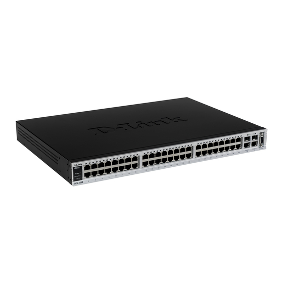
The front panel of the Switch consists of LED indicators for power and for each 10/100 Mbps twisted-pair ports, and two 1000BASE-T Mini-GBIC ports. DES-3550 Figure 1- 1. Front Panel View of the DES-3550 as shipped Comprehensive LED indicators display the status of the Swtch and the network. LED Indicators The LED indicators of the Switch include Power, Console, Link/Act, Speed, and FDX. -
Page 18: Rear Panel Description
DES-3550 Layer 2 Fast Ethernet Switch User’s Guide Rear Panel Description The rear panel of the Switch contains an AC power connector. Figure 1- 3. Rear panel view of the Switch The AC power connector is a standard three-pronged connector that supports the power cord. - Page 19 DES-3550 Layer 2 Fast Ethernet Switch User’s Guide Figure 1- 5. Mini-GBIC modules plug-in to the Switch Figure 1- 6. Installing the Mini-GBIC Module...
-
Page 20: Installation
• RS-232 console cable • If any item is found missing or damaged, please contact your local D-Link Reseller for replacement. Before You Connect to the Network The site where you install the Switch may greatly affect its performance. Please follow these guidelines for setting up the Switch. -
Page 21: Installing The Switch Without The Rack
DES-3550 Layer 2 Fast Ethernet Switch User’s Guide • When installing the Switch on a level surface, attach the rubber feet to the bottom of the device. The rubber feet cushion the Switch, protect the casing from scratches, and prevent it from scratching other surfaces. -
Page 22: Mounting The Switch In A Standard 19" Rack
DES-3550 Layer 2 Fast Ethernet Switch User’s Guide Fasten the mounting brackets to the Switch using the screws provided. With the brackets attached securely, you can mount the Switch in a standard rack as shown in Figure 2-3, below. Mounting the Switch in a standard 19” rack. -
Page 23: Connecting The Switch
DES-3550 Layer 2 Fast Ethernet Switch User’s Guide Section 3 Connecting The Switch Switch To End Node Switch To Hub or Switch Connecting To Network Backbone or Server NOTE: All 48 high-performance NWay Ethernet ports can support both MDI-II and MDI-X connections. -
Page 24: Connecting To Network Backbone Or Server
DES-3550 Layer 2 Fast Ethernet Switch User’s Guide Figure 3- 2. Switch connected to a port on a hub or switch using either a straight or crossover cable– any normal cable is fine Connecting To Network Backbone or Server The two Mini-GBIC combo ports are ideal for uplinking to a network backbone or server. The copper ports operate at a speed of 1000, 100, or 10Mbps in ful-l or half-duplex mode. -
Page 25: Introduction To Switch Management
DES-3550 Layer 2 Fast Ethernet Switch User’s Guide Section 4 Introduction To Switch Management Management Options Web-based Management Interface SNMP-Based Management Managing User Accounts Command Line Console Interface Through The Serial Port Connecting the Console Port (RS-232 DCE) First Time Connecting to The Switch... - Page 26 11. Enter the commands to complete your desired tasks. Many commands require administrator-level access privileges. Read the next section for more information on setting up user accounts. See the DES-3550 Command Line Interface Reference Manual on the documentation CD for a list of all commands and additional information on using the CLI.
-
Page 27: First Time Connecting To The Switch
DES-3550 Layer 2 Fast Ethernet Switch User’s Guide Settings tab. This is where you will find the Emulation options. If you still do not see anything, try rebooting the Switch by disconnecting its power supply. Once connected to the console, the screen below will appear on your console screen. This is where the user will enter commands to perform all the available management functions. - Page 28 Figure 4- 2. Initial screen, first time connecting to the Switch Press Enter in both the Username and Password fields. You will be given access to the command prompt DES-3550:4# shown below: There is no initial username or password. Leave the Username and Password fields blank.
-
Page 29: Password Protection
Fast Ethernet Switch User’s Guide Password Protection The DES-3550 does not have a default user name and password. One of the first tasks when settings up the Switch is to create user accounts. If you log in using a predefined administrator-level user name, you have privileged access to the Switch’s management... - Page 30 The DES-3550 supports SNMP versions 1, 2c, and 3. You can specify which version of SNMP you want to use to monitor and control the Switch. The three versions of SNMP vary in the level of security provided between the management station and the network device.
-
Page 31: Ip Address Assignment
DES-3550 Layer 2 Fast Ethernet Switch User’s Guide MIBs Management and counter information are stored by the Switch in the Management Information Base (MIB). The Switch uses the standard MIB-II Management Information Base module. Consequently, values for MIB objects can be retrieved from any SNMP-based network management software. -
Page 32: Connecting Devices To The Switch
DES-3550 Layer 2 Fast Ethernet Switch User’s Guide to be assigned to the IP interface named System and the y’s represent the corresponding subnet mask. 2. Alternatively, you can enter config ipif System ipaddress xxx.xxx.xxx.xxx/z. Where the x’s represent the IP address to be assigned to the IP interface named System and the z represents the corresponding number of subnets in CIDR notation. - Page 33 DES-3550 Layer 2 Fast Ethernet Switch User’s Guide...
-
Page 34: Introduction To Web-Based Switch Configuration
Network Management Switch Utilities Network Monitoring IGMP Snooping Status Introduction All software functions of the DES-3550 can be managed, configured, and monitored via the embedded web-based (HTML) interface. The Switch can be managed from remote stations anywhere network through standard... -
Page 35: Web-Based User Interface
DES-3550 Layer 2 Fast Ethernet Switch User’s Guide Leave both the User Name field and the Password field blank and click OK. This will open the Web-based user interface. The Switch management features available in the web-based manager are explained below. - Page 36 Select the menu or window to be displayed. The folder icons can be opened to display the hyperlinked menu buttons and subfolders contained within them. Click the D-Link logo to go to the D-Link website. Presents switch information based on your selection and the entry of configuration data.
-
Page 37: Configuring The Switch
DES-3550 Layer 2 Fast Ethernet Switch User’s Guide Section 6 Configuring The Switch IP Address Switch Information Advanced Settings Port Configuration Port Mirroring Port Description IGMP Spanning Tree Forward Filtering VLANs Port Bandwidth SNTP Settings Port Security MAC Notification LACP... - Page 38 DES-3550 Layer 2 Fast Ethernet Switch User’s Guide Figure 6- 1. IP Address Settings window. To manually assign the Switch’s IP address, subnet mask, and default gateway address: • Select Manual from the Get IP From drop-down menu. • Enter the appropriate IP address and subnet mask.
- Page 39 DES-3550 Layer 2 Fast Ethernet Switch User’s Guide BOOTP or DHCP protocols to assign the Switch an IP address, subnet mask, and default gateway address: Use the Get IP From: <Manual> pull-down menu to choose from BOOTP or DHCP. This selects how the Switch will be assigned an IP address on the next reboot.
-
Page 40: Switch Information
DES-3550 Layer 2 Fast Ethernet Switch User’s Guide Setting the Switch’s IP Address using the Console Interface Each Switch must be assigned its own IP Address, which is used for communication with an SNMP network manager or other TCP/IP application (for example BOOTP, TFTP). The Switch’s default IP address is 10.90.90.90. -
Page 41: Advanced Settings
DES-3550 Layer 2 Fast Ethernet Switch User’s Guide Figure 6- 2. Switch Information – Basic Settings The Switch Information window shows the Switch’s MAC Address (assigned by the factory and is unchangeable), IP configuration, some important functions implemented, and their status. - Page 42 DES-3550 Layer 2 Fast Ethernet Switch User’s Guide Figure 6- 3. Switch Information (Advanced Settings) Parameter Description Serial Port Auto Select the logout time used for the console interface. This automatically logs Logout Time the user out after an idle period of time, as defined. Choose from the following options: 2 Minutes, 5 Minutes, 10 Minutes, 15 Minutes, or Never.
-
Page 43: Port Configurations
DES-3550 Layer 2 Fast Ethernet Switch User’s Guide RMON Status Remote monitoring (RMON) of the Switch is Enabled or Disabled here. 802.1x Status Enables or disables 802.1x; default is Disabled. 802.1x The user may use the pull down menu to choose between Radius Eap and Authentication Radius Pap for the 802.1x authentication protocol on the Switch. - Page 44 DES-3550 Layer 2 Fast Ethernet Switch User’s Guide Figure 6- 4. Port Configuration and The Port Information Table window...
-
Page 45: Port Mirroring
DES-3550 Layer 2 Fast Ethernet Switch User’s Guide To configure switch ports: 1. Choose the port or sequential range of ports using the From…To… port pull-down menus. 2. Use the remaining pull-down menus to configure the parameters described below: Parameter Description State <Enabled>... -
Page 46: Port Description
Please note a target port and a source port cannot be the same port. Port Description The DES-3550 supports a port description feature where the user may name various ports on the Switch. To assign names to various ports, click the Port Description on the Configuration menu:... - Page 47 DES-3550 Layer 2 Fast Ethernet Switch User’s Guide Figure 6- 6. Port Description Setting and Port Description Table Use the From and To pull down menu to choose a port or range of ports to describe, and then enter a description of the port(s). Click Apply to set the descriptions in the Port Description...
-
Page 48: Igmp
DES-3550 Layer 2 Fast Ethernet Switch User’s Guide IGMP Internet Group Management Protocol (IGMP) snooping allows the Switch to recognize IGMP queries and reports sent between network stations or devices and an IGMP host. When enabled for IGMP snooping, the Switch can open or close a port to a specific device based on IGMP messages passing through the Switch. -
Page 49: Static Router Ports
DES-3550 Layer 2 Fast Ethernet Switch User’s Guide Parameter Description VLAN ID This is the VLAN ID that, along with the VLAN name, identifies the VLAN that the user wishes to modify the IGMP Snooping Settings for. This is the VLAN Name that, along with the VLAN ID, identifies the VLAN VLAN Name that the user wishes to modify the IGMP Snooping Settings for. - Page 50 DES-3550 Layer 2 Fast Ethernet Switch User’s Guide • All IGMP Report packets will be forwarded to the router port. • IGMP queries (from the router port) will be flooded to all ports. • All UDP multicast packets will be forwarded to the router port. Because routers do not...
-
Page 51: Spanning Tree
Protocol (RSTP). 802.1d STP will be familiar to most networking professionals. However since 802.1w RSTP has been recently introduced to D-Link managed Ethernet switches, a brief introduction to the technology is provided below followed by a description of how to set up 802.1 d STP and 802.1w RSTP. -
Page 52: Stp Switch Settings
DES-3550 Layer 2 Fast Ethernet Switch User’s Guide RSTP is capable of more rapid transition to a forwarding state; it no longer relies on timer configurations. RSTP compliant bridges are sensitive to feedback from other RSTP compliant bridge links. Ports do not need to wait for the topology to stabilize before transitioning to a forwarding state. - Page 53 DES-3550 Layer 2 Fast Ethernet Switch User’s Guide Figure 6- 11. STP Switch Settings Configure the following parameters and click the Apply button to implement them: Parameter Description This field can be toggled between Enabled and Disabled using the pull-down Spanning Tree menu.
-
Page 54: Stp Port Settings
DES-3550 Layer 2 Fast Ethernet Switch User’s Guide Bridge Forward The Forward Delay can be from 4 to 30 seconds. This is the time any port on Delay: (4 - 30 sec) the Switch spends in the listening state while moving from the blocking state <15 >... - Page 55 DES-3550 Layer 2 Fast Ethernet Switch User’s Guide Figure 6- 12. STP Port Settings and The STP Port Information window...
- Page 56 DES-3550 Layer 2 Fast Ethernet Switch User’s Guide In addition to setting Spanning Tree parameters for use on the switch level, the Switch allows for the configuration of groups of ports, each port-group of which will have its own spanning tree, and will require some of its own configuration settings.
-
Page 57: Forwarding Filtering
DES-3550 Layer 2 Fast Ethernet Switch User’s Guide Forwarding Filtering Unicast Forwarding Open the Forwarding Filtering folder in the Configuration menu and click on the Unicast Forwarding link. This will open the Setup Static Unicast Forwarding Table, as shown below: Figure 6- 13. -
Page 58: Multicast Port Filtering
DES-3550 Layer 2 Fast Ethernet Switch User’s Guide Figure 6- 15. Setup Static Multicast Forwarding Table The following parameters can be set: Parameter Description The VLAN ID of the VLAN the corresponding MAC address belongs to. Multicast MAC The MAC address of the static source of multicast packets. This must be a Address multicast MAC address. - Page 59 DES-3550 Layer 2 Fast Ethernet Switch User’s Guide Figure 6- 16. Multicast Port Filtering Mode Setup and Multicast port Filtering Mode Table...
-
Page 60: Vlans
DES-3550 Layer 2 Fast Ethernet Switch User’s Guide The following parameters can be set: Parameter Description These two drop-down menus allow you to select a range of ports that the From/To filter settings will be applied to. This drop-down menu allows you to select the action the Switch will take when it receives a multicast packet that is to be forwarded to one of the ports in the range specified above. -
Page 61: Vlans
VLANs without a network device performing a routing function between the VLANs. The DES-3550 supports IEEE 802.1Q VLANs and Port-Based VLANs. The port untagging function can be used to remove the 802.1Q tag from packet headers to maintain compatibility with devices that are tag-unaware. - Page 62 DES-3550 Layer 2 Fast Ethernet Switch User’s Guide Egress port – A port on a switch where packets are flowing out of the switch, either to another switch or to an end station, and tagging decisions must be made. IEEE 802.1Q (tagged) VLANs are implemented on the Switch. 802.1Q VLANs require tagging, which enables them to span the entire network (assuming all switches on the network are IEEE 802.1Q-compliant).
- Page 63 DES-3550 Layer 2 Fast Ethernet Switch User’s Guide Figure 6- 17. IEEE 802.1Q Packet Forwarding 802.1Q VLAN Tags The figure below shows the 802.1Q VLAN tag. There are four additional octets inserted after the source MAC address. Their presence is indicated by a value of 0x8100 in the EtherType field.
- Page 64 DES-3550 Layer 2 Fast Ethernet Switch User’s Guide Figure 6- 18. IEEE 802.1Q Tag The EtherType and VLAN ID are inserted after the MAC source address, but before the original EtherType/Length or Logical Link Control. Because the packet is now a bit longer than it was originally, the Cyclic Redundancy Check (CRC) must be recalculated.
- Page 65 DES-3550 Layer 2 Fast Ethernet Switch User’s Guide forwarding table). If the PVID of the port that received the packet is different from the PVID of the port that is to transmit the packet, the Switch will drop the packet.
- Page 66 DES-3550 Layer 2 Fast Ethernet Switch User’s Guide Ingress Filtering A port on a switch where packets are flowing into the switch and VLAN decisions must be made is referred to as an ingress port. If ingress filtering is enabled for a port, the switch will examine the VLAN information in the packet header (if present) and decide whether or not to forward the packet.
-
Page 67: Port-Based Vlans
DES-3550 Layer 2 Fast Ethernet Switch User’s Guide Port-based VLANs Port-based VLANs limit traffic that flows into and out of switch ports. Thus, all devices connected to a port are members of the VLAN(s) the port belongs to, whether there is a single computer directly connected to a switch, or an entire department. - Page 68 DES-3550 Layer 2 Fast Ethernet Switch User’s Guide Figure 6- 20. Current 802.1Q Static VLANs Entries window The 802.1Q Static VLANs menu lists all previously configured VLANs by VLAN ID and name. To delete an existing 802.1Q VLAN, click the corresponding button under the Delete heading.
- Page 69 DES-3550 Layer 2 Fast Ethernet Switch User’s Guide Figure 6- 22. 802.1Q Static VLANs Entry Settings – Modify The following fields can then be set in either the Add or Modify 802.1Q Static VLANs menus: Parameter Description VID (VLAN ID) Allows the entry of a VLAN ID in the Add dialog box, or displays the VLAN ID of an existing VLAN in the Edit dialog box.
-
Page 70: Port Vlan Id(Pvid)
DES-3550 Layer 2 Fast Ethernet Switch User’s Guide Port VLAN ID(PVID) In the Configuration menu, open the VLANs folder and click Port VLAN ID. The 802.1Q Port Settings dialog box, shown below, allows you to determine whether the Switch will share its VLAN configuration information with other GARP VLAN Registration Protocol (GVRP) enabled switches. -
Page 71: Port Bandwidth
DES-3550 Layer 2 Fast Ethernet Switch User’s Guide The following fields can be set: Parameter Description These two fields allow you to specify the range of ports that will be included From/To in the Port-based VLAN that you are creating using the 802.1Q Port Settings page. - Page 72 DES-3550 Layer 2 Fast Ethernet Switch User’s Guide Figure 6- 24. Bandwidth Settings and Port Bandwidth Table...
-
Page 73: Sntp Settings
DES-3550 Layer 2 Fast Ethernet Switch User’s Guide The following parameters can be set or are displayed: Parameter Description A consecutive group of ports may be configured starting with the selected From/To port. This drop-down menu allows you to select between RX (receive), TX (transmit), and Both. -
Page 74: Time Zone And Dst
DES-3550 Layer 2 Fast Ethernet Switch User’s Guide Parameter Description Current Time Displays the time when the Switch was initially started for this session. Time Source Displays the time source for the system. SNTP State Use this pull-down menu to Enable or Disable SNTP. - Page 75 DES-3550 Layer 2 Fast Ethernet Switch User’s Guide Figure 6- 26. Time Zone and DST Settings Page The following parameters can be set: Parameter Description Daylight Saving Time Use this pull-down menu to Enable or Disable the DST Settings. State...
-
Page 76: Port Security
DES-3550 Layer 2 Fast Ethernet Switch User’s Guide From: Day of Week Enter the day of the week that DST will start on. From: Month Enter the month DST will start on. From: time in HH:MM Enter the time of day that DST will start on. - Page 77 DES-3550 Layer 2 Fast Ethernet Switch User’s Guide Figure 6- 27. Port Security Settings window...
-
Page 78: Qos
CoS queues that have been given a nonzero value, and depending upon the weight, will follow a common weighted round-robin scheme. Remember that the DES-3550 has 4 priority queues (and four Classes of Service) for each port on the Switch. -
Page 79: Traffic Control
DES-3550 Layer 2 Fast Ethernet Switch User’s Guide Traffic Control Use the Traffic Control menu to enable or disable storm control and adjust the threshold for multicast and broadcast storms, as well as DLF (Destination Look Up Failure). Traffic control settings are applied to individual Switch modules. - Page 80 DES-3550 Layer 2 Fast Ethernet Switch User’s Guide Figure 6- 29. 802.1p Default Priority window This page allows you to assign a default 802.1p priority to any given port on the Switch. The priority queues are numbered from 0, the lowest priority, to 7, the highest priority. Click...
-
Page 81: 802.1P User Priority
Fast Ethernet Switch User’s Guide 802.1p User Priority The DES-3550 allows the assignment of a user priority to each of the 802.1p priorities. In the Configuration folder open the QoS folder and click 802.1p User Priority, to view the screen shown below. -
Page 82: Traffic Segmentation
DES-3550 Layer 2 Fast Ethernet Switch User’s Guide priority queue will be allowed to transmit before allowing the next lowest priority queue to transmit its packets. A value between 0 and 255 can be specified. Max. Latency(0-255) Specifies the maximum amount of time the above specified hardware priority queue will be allowed to transmit packets before allowing the next lowest hardware priority queue to begin transmitting its packets. - Page 83 DES-3550 Layer 2 Fast Ethernet Switch User’s Guide Figure 6- 32. Traffic Segmentation Setting and Traffic Segmentation Table window...
-
Page 84: Mac Notification
DES-3550 Layer 2 Fast Ethernet Switch User’s Guide This page allows you to determine which port on a given switch will be allowed to forward packets to other ports on that switch. The user may set the following parameters: Parameter... - Page 85 DES-3550 Layer 2 Fast Ethernet Switch User’s Guide Figure 6- 34. MAC Notification Port Settings and Port State Table...
-
Page 86: Lacp
Port trunk groups are used to combine a number of ports together to make a single high- bandwidth data pipeline. The DES-3550 supports up to 6 port trunk groups with 2 to 8 ports in each group. A potential bit rate of 8000 Mbps can be achieved. - Page 87 DES-3550 Layer 2 Fast Ethernet Switch User’s Guide Note: If any ports within the trunk group become disconnected, packets intended for the disconnected port will be load shared among the other uplinked ports of the link aggregation group. Link aggregation allows several ports to be grouped together and to act as a single link. This gives a bandwidth that is a multiple of a single link’s bandwidth.
- Page 88 DES-3550 Layer 2 Fast Ethernet Switch User’s Guide Figure 6- 37. Link Aggregation Settings window – Add Figure 6- 38. Link Aggregation Group Configuration window – Modify The user-changeable parameters are as follows: Parameter Description Group ID Select an ID number for the group, between 1 and 6.
-
Page 89: Lacp Port
DES-3550 Layer 2 Fast Ethernet Switch User’s Guide Flooding Port A trunking group must designate one port to allow transmission of broadcasts and unknown unicasts. Active Port Shows the port that is currently forwarding packets. Type This pull-down menu allows you to select between Static and LACP (Link Aggregation Control Protocol). - Page 90 DES-3550 Layer 2 Fast Ethernet Switch User’s Guide Figure 6- 39. Lacp Port Settings and LACP Port Table...
-
Page 91: Access Profile Table
DES-3550 Layer 2 Fast Ethernet Switch User’s Guide The user may set the following parameters: Parameter Description From/To A consecutive group of ports may be configured starting with the selected port. Mode Active – Active LACP ports are capable of processing and sending LACP control frames. - Page 92 DES-3550 Layer 2 Fast Ethernet Switch User’s Guide Figure 6- 41. Access Profile Table (Ethernet) The following parameters can be set for Ethernet: Parameter Description Type in a unique identifier number for this profile set. This value can be set Profile ID (1-255) from 1 –...
- Page 93 DES-3550 Layer 2 Fast Ethernet Switch User’s Guide Figure 6- 42. Access Profile Configuration (IP) The following parameters can be set for IP: Parameter Description Type in a unique identifier number for this profile set. This value can be set Profile ID(1-255) from 1 –...
- Page 94 DES-3550 Layer 2 Fast Ethernet Switch User’s Guide Source IP Mask Source IP Mask - Enter an IP address mask for the source IP address. Destination IP Mask - Enter an IP address mask for the destination IP Destination IP Mask address.
- Page 95 DES-3550 Layer 2 Fast Ethernet Switch User’s Guide Figure 6- 43. Access Profile Configuration window (Packet Content Mask) This screen will aid the user in configuring the Switch to mask packet headers beginning with the offset value specified. The following fields are used to configure the Packet Content...
- Page 96 DES-3550 Layer 2 Fast Ethernet Switch User’s Guide the offset value specified: value(0-15) - Enter a value in hex form to mask the packet from the beginning of the packet to the 16 byte. value(16-31) - Enter a value in hex form to mask the packet from byte 16 to byte 31.
- Page 97 DES-3550 Layer 2 Fast Ethernet Switch User’s Guide Figure 6- 45. Access Rule Configuration window (IP) Configure the following Access Rule Configuration settings: Parameter Description Profile ID This is the identifier number for this profile set. Mode Select Permit to specify that the packets that match the access profile are forwarded by the Switch, according to any additional rule added (see below).
- Page 98 DES-3550 Layer 2 Fast Ethernet Switch User’s Guide Dscp(0-63) This field allows the user to enter a Dscp value in the space provided, which will instruct the Switch to examine the DiffServ Code part of each packet header and use this as the, or part of the criterion for forwarding. The user may choose a value between 0 and 63.
- Page 99 DES-3550 Layer 2 Fast Ethernet Switch User’s Guide Figure 6- 48. Access Rule Configuration window (Ethernet). To set the Access Rule for Ethernet, adjust the following parameters and click Apply. Parameters Description Profile ID This is the identifier number for this profile set.
- Page 100 DES-3550 Layer 2 Fast Ethernet Switch User’s Guide 802.1p(0-7) Enter a value from 0-7 to specify that the access profile will apply only to packets with this 802.1p priority value. Ethernet Type Specifies that the access profile will apply only to packets with this hexadecimal 802.1Q Ethernet type value (hex 0x0-0xffff) in the...
- Page 101 DES-3550 Layer 2 Fast Ethernet Switch User’s Guide Figure 6- 51. Access Rule Configuration (Packet Content Mask) To set the Access Rule for the Packet Content Mask, adjust the following parameters and click Apply. Parameter Description Profile ID This is the identifier number for this profile set.
- Page 102 DES-3550 Layer 2 Fast Ethernet Switch User’s Guide Priority Select this option to instruct the Switch to use the 802.1p priority value entered in the adjacent field for packets that meet the criteria. A number between 0, the lowest priority, and 7, the highest priority, can be entered.
-
Page 103: System Log Server
DES-3550 Layer 2 Fast Ethernet Switch User’s Guide System Log Server The Switch can send Syslog messages to up to four designated servers using the System Log Server. In the Configuration folder, click System Log Server, to view the screen shown below. -
Page 104: Pae Access Entity (802.1X)
DES-3550 Layer 2 Fast Ethernet Switch User’s Guide Numerical Facility Code kernel messages user-level messages mail system system daemons security/authorization messages messages generated internally by syslog line printer subsystem network news subsystem UUCP subsystem clock daemon security/authorization messages FTP daemon... - Page 105 DES-3550 Layer 2 Fast Ethernet Switch User’s Guide Figure 6- 55. Typical 802.1x Configuration Prior to User Authentication Once the user is authenticated, the Switch unblocks the port that is connected to the user as shown in the next figure.
-
Page 106: Configure Authenticator
The Key Receive state machine Table 6- 2. Conformance to IEEE 802.1x Standards The DES-3550 implements the server-side of the IEEE 802.1x Port-based Network Access Control. This mechanism is intended to allow only authorized users, or other network devices, access to network resources by establishing criteria for each port on the Switch that a user or network device must meet before allowing that port to forward or receive frames. - Page 107 DES-3550 Layer 2 Fast Ethernet Switch User’s Guide Figure 6- 58. 802.1X Authenticator Settings window...
- Page 108 DES-3550 Layer 2 Fast Ethernet Switch User’s Guide To configure the settings by port, click on the hyperlinked port number under the Port heading, which will display the following table to configure: Figure 6- 59. 802.1X Authenticator Settings - Modify...
-
Page 109: Port Capability Settings
DES-3550 Layer 2 Fast Ethernet Switch User’s Guide TxPeriod:[30 ] This sets the TxPeriod of time for the authenticator PAE state machine. This value determines the period of an EAP Request/Identity packet transmitted to the client. QuietPeriod:[60 ] This allows you to set the number of seconds that the Switch remains in the quiet state following a failed authentication exchange with the client. - Page 110 DES-3550 Layer 2 Fast Ethernet Switch User’s Guide Figure 6- 60. 802.1x Capability Settings and Table window...
-
Page 111: Initializing Ports
DES-3550 Layer 2 Fast Ethernet Switch User’s Guide To set up the Switch’s 802.1x port-based authentication, select which ports are to be configured in the From and To fields. Next, enable the ports by selecting Authenticator from the drop-down menu under Capability. Click Apply to make your change take effect. -
Page 112: Reauthenticate Port(S)
DES-3550 Layer 2 Fast Ethernet Switch User’s Guide From and To Select ports to be initialized. Port A read only field indicating a port on the Switch. MAC Address The MAC address of the Switch connected to the corresponding port, if any. -
Page 113: Radius Server
DES-3550 Layer 2 Fast Ethernet Switch User’s Guide Port The port number. MAC Address Displays the physical address of the Switch where the port resides. Auth State The Authenticator State will display one of the following: Initialize, Disconnected, Connecting, Authenticating, Authenticated, Aborting, Held, ForceAuth, ForceUnauth, and N/A. - Page 114 DES-3550 Layer 2 Fast Ethernet Switch User’s Guide Succession <First> Choose the desired RADIUS server to configure: First, Second, or Third. Radius Server Set the RADIUS server IP. <10.53.13.94> Authentic Port Set the RADIUS authentic server(s) UDP port. The default is 1812.
-
Page 115: Management
DES-3550 Layer 2 Fast Ethernet Switch User’s Guide Section 7 Management Security IP User Accounts Access Authentication Control (TACACS) SNMP V3 The following section will aid the user in configuring security functions for the Switch. The Switch includes various functions for security, including TACACS, Security IPs, and SNMP, all discussed in detail in the following section. - Page 116 DES-3550 Layer 2 Fast Ethernet Switch User’s Guide Figure 7- 3. User Accounts Modify Table - Add Add a new user by typing in a User Name and New Password and retype the same password in the Confirm New Password. Choose the level of privilege (Admin or User) from the Access Right drop-down menu.
-
Page 117: Access Authentication Control
DES-3550 Layer 2 Fast Ethernet Switch User’s Guide User Account Management Add/Update/Delete User Accounts View User Accounts Admin and User Privileges After establishing a User Account with Admin-level privileges, be sure to save the changes by opening the Maintenance folder, opening the Save Changes window and clicking the Save Configuration button. -
Page 118: Policy & Parameters
DES-3550 Layer 2 Fast Ethernet Switch User’s Guide Hosts in a preferable order in the built-in Authentication Server Groups and when a user tries to gain access to the Switch, the Switch will ask the first Authentication Server Hosts for authentication. -
Page 119: Application's Authentication Settings
DES-3550 Layer 2 Fast Ethernet Switch User’s Guide Switch will accept authentication attempts. Users failing to be authenticated after the set amount of attempts will be denied access to the Switch and will be locked out of further authentication attempts. Command line interface users will have to wait 60 seconds before another authentication attempt. -
Page 120: Authentication Server Hosts
DES-3550 Layer 2 Fast Ethernet Switch User’s Guide To view the following window, click Management > Access Authentication Control > Authentication Server Group: Figure 7- 7. Authentication Server Group Settings window This screen displays the Authentication Server Groups on the Switch. The Switch has three built-in Authentication Server Groups that cannot be removed but can be modified. - Page 121 DES-3550 Layer 2 Fast Ethernet Switch User’s Guide appropriate message to the Switch. More than one authentication protocol can be run on the same physical server host but, remember that are separate TACACS/XTACACS/TACACS+ entities and are not compatible with each other. The maximum supported number of server hosts is 16.
-
Page 122: Login Method Lists
DES-3550 Layer 2 Fast Ethernet Switch User’s Guide Retransmit(1-255) Enter the value in the retransmit field to change how many times the device will resend an authentication request when the TACACS server does not respond. Authentication key to be shared with a configured TACACS+ server only. - Page 123 DES-3550 Layer 2 Fast Ethernet Switch User’s Guide Figure 7- 12. Login Method List –Edit (default) Figure 7- 13. Login Method List – Add To define a Login Method List, set the following parameters and click Apply: Parameter Description Method List Name Enter a method list name defined by the user of up to 15 characters.
-
Page 124: Enable Method Lists
DES-3550 Layer 2 Fast Ethernet Switch User’s Guide Enable Method Lists This window is used to set up Method Lists to promote users with normal level privileges to Administrator level privileges using authentication methods on the Switch. Once a user... - Page 125 DES-3550 Layer 2 Fast Ethernet Switch User’s Guide Figure 7- 15. Enable Method List – Edit window Figure 7- 16. Enable Method List – Add window To define an Enable Login Method List, set the following parameters and click Apply:...
-
Page 126: Local Enable Password
DES-3550 Layer 2 Fast Ethernet Switch User’s Guide Local Enable Password This window will configure the locally enabled password for the Enable Admin command. When a user chooses the “Local_Enable” method to promote user level privileges to administrator privileges, he or she will be prompted to enter the password configured here that is locally set on the Switch. -
Page 127: Snmp
The DES-3550 supports the SNMP versions 1, 2c, and 3. You can specify which version of the SNMP you want to use to monitor and control the Switch. The three versions of SNMP vary in the level of security provided between the management station and the network device. - Page 128 Use the SNMP V3 menus to select the SNMP version used for specific tasks. The DES-3550 supports the Simple Network Management Protocol (SNMP) versions 1, 2c, and 3. The administrator can specify the SNMP version used to monitor and control the Switch.
-
Page 129: Snmp User Table
DES-3550 Layer 2 Fast Ethernet Switch User’s Guide SNMP settings are configured using the menus located on the SNMP V3 folder of the web manager. Workstations on the network that are allowed SNMP privileged access to the Switch can be restricted with the Management Station IP Address menu. - Page 130 DES-3550 Layer 2 Fast Ethernet Switch User’s Guide None − Indicates that no authorization protocol is in use. MD5 − Indicates that the HMAC-MD5-96 authentication level will be used. Auth-Protocol SHA − Indicates that the HMAC-SHA authentication protocol will be used None −...
-
Page 131: Snmp View Table
DES-3550 Layer 2 Fast Ethernet Switch User’s Guide Checking the corresponding box will enable encryption for SNMP V3 and is encrypted only operable in SNMP V3 mode. To implement the changes, click Apply. To return to the SNMP User Table, click the... -
Page 132: Snmp Group Table
DES-3550 Layer 2 Fast Ethernet Switch User’s Guide View Name Type an alphanumeric string of up to 32 characters. This is used to identify the new SNMP view being created. Subtree OID Type the Object Identifier (OID) Subtree for the view. The OID identifies an object tree (MIB tree) that will be included or excluded from access by an SNMP manager. - Page 133 DES-3550 Layer 2 Fast Ethernet Switch User’s Guide Figure 7- 26. SNMP Group Table Display To add a new entry to the Switch’s SNMP Group Table, click the Add button in the upper left-hand corner of the SNMP Group Table page. This will open the SNMP Group Table Configuration page, as shown below.
-
Page 134: Snmp Community Table Configuration
DES-3550 Layer 2 Fast Ethernet Switch User’s Guide and adds some security features. SNMPv3 – Specifies that the SNMP version 3 will be used. SNMPv3 provides secure access to devices through a combination of authentication and encrypting packets over the network. -
Page 135: Snmp Host Table
DES-3550 Layer 2 Fast Ethernet Switch User’s Guide remote SNMP managers access to MIB objects in the Switch’s SNMP agent. View Name Type an alphanumeric string of up to 32 characters that is used to identify the group of MIB objects that a remote SNMP manager is allowed to access on the Switch. -
Page 136: Snmp Engine Id
DES-3550 Layer 2 Fast Ethernet Switch User’s Guide SNMP host for the Switch. SNMP Version V1 – To specify that SNMP version 1 will be used. V2 – To specify that SNMP version 2 will be used. V3-NoAuth-NoPriv – To specify that the SNMP version 3 will be used, with a NoAuth-NoPriv security level. -
Page 137: Monitoring
DES-3550 Layer 2 Fast Ethernet Switch User’s Guide Section 8 Monitoring Port Utilization CPU Utilization Packets Errors Size MAC Address IGMP Snooping Group IGMP Snooping Forwarding VLAN Status Router Port Port Access Control Port Utilization The Port Utilization page displays the percentage of the total available bandwidth being used on the port. -
Page 138: Cpu Utilization
DES-3550 Layer 2 Fast Ethernet Switch User’s Guide Parameter Description Select the desired setting between 1s and 60s, where “s” stands for Time Interval seconds. The default value is one second. Select number of times the Switch will be polled between 20 and 200. The Record Number default value is 200. -
Page 139: Packets
DES-3550 Layer 2 Fast Ethernet Switch User’s Guide Packets The Web Manager allows various packet statistics to be viewed as either a line graph or a table. Six windows are offered. Received(RX) Click the Received(RX) link in the Packets folder of the Monitoring menu to view the following graph of packets received on the Switch. - Page 140 DES-3550 Layer 2 Fast Ethernet Switch User’s Guide Figure 8- 4. Rx Packets Analysis window (table for Bytes and Packets) The following fields may be set or viewed: Parameter Description Time Interval [1s ] Select the desired setting between 1s and 60s, where “s” stands for seconds.
-
Page 141: Umb_Cast(Rx)
DES-3550 Layer 2 Fast Ethernet Switch User’s Guide UMB_cast(RX) Click the UMB_cast(RX) link in the Packets folder of the Monitoring menu to view the following graph of UMB cast packets received on the Switch. Figure 8- 5. Rx Packets Analysis window (line graph for Unicast, Multicast, and Broadcast Packets) - Page 142 DES-3550 Layer 2 Fast Ethernet Switch User’s Guide Figure 6- 64. Rx Packets Analysis window (table for Unicast, Multicast, and Broadcast Packets) The following fields may be set or viewed: Parameter Description Time Interval [1s ] Select the desired setting between 1s and 60s, where “s” stands for seconds.
-
Page 143: Transmitted (Tx)
DES-3550 Layer 2 Fast Ethernet Switch User’s Guide Transmitted (TX) Click the Transmitted (TX) link in the Packets folder of the Monitoring menu to view the following graph of packets transmitted from the Switch. Figure 8- 6. Tx Packets Analysis window (line graph for Bytes and Packets) - Page 144 DES-3550 Layer 2 Fast Ethernet Switch User’s Guide Figure 8- 7. Tx Packets Analysis window (table for Bytes and Packets) The following fields may be set or viewed: Parameter Description Time Interval [1s ] Select the desired setting between 1s and 60s, where “s” stands for seconds.
-
Page 145: Errors
DES-3550 Layer 2 Fast Ethernet Switch User’s Guide Errors The Web Manager allows port error statistics compiled by the Switch’s management agent to be viewed as either a line graph or a table. Four windows are offered. Received (RX) Click the Received (RX) link in the Error folder of the Monitoring menu to view the following graph of error packets received on the Switch. - Page 146 DES-3550 Layer 2 Fast Ethernet Switch User’s Guide Figure 8- 9. Rx Error Analysis window (table) The following fields can be set: Parameter Description Time Interval [1s ] Select the desired setting between 1s and 60s, where “s” stands for seconds.
-
Page 147: Transmitted (Tx)
DES-3550 Layer 2 Fast Ethernet Switch User’s Guide Clear Clicking this button clears all statistics counters on this window. View Table Clicking this button instructs the Switch to display a table rather than a line graph. View Line Chart Clicking this button instructs the Switch to display a line graph rather than a table. - Page 148 DES-3550 Layer 2 Fast Ethernet Switch User’s Guide Figure 8- 11. Tx Error Analysis window (table) The following fields may be set or viewed: Parameter Description Time Interval [1s ] Select the desired setting between 1s and 60s, where “s” stands for seconds.
-
Page 149: Size
DES-3550 Layer 2 Fast Ethernet Switch User’s Guide Size The Web Manager allows packets received by the Switch, arranged in six groups and classed by size, to be viewed as either a line graph or a table. Two windows are offered. -
Page 150: Mac Address
DES-3550 Layer 2 Fast Ethernet Switch User’s Guide The following fields can be set or viewed: Parameter Description Time Interval [1s ] Select the desired setting between 1s and 60s, where “s” stands for seconds. The default value is one second. - Page 151 DES-3550 Layer 2 Fast Ethernet Switch User’s Guide Figure 8- 14. MAC Address Table The following fields can be viewed or set: Parameter Description VLAN ID Enter a VLAN ID for the forwarding table to be browsed by. MAC Address Enter a MAC address for the forwarding table to be browsed by.
-
Page 152: Igmp Snooping Group
DES-3550 Layer 2 Fast Ethernet Switch User’s Guide IGMP Snooping Group IGMP Snooping allows the Switch to read the Multicast Group IP address and the corresponding MAC address from IGMP packets that pass through the Switch. The number of IGMP reports that were snooped is displayed in the Reports field. -
Page 153: Igmp Snooping Forwarding
DES-3550 Layer 2 Fast Ethernet Switch User’s Guide IGMP Snooping Forwarding This window will display the current IGMP snooping forwarding table entries currently configured on the Switch. To view the following screen, open the Monitoring folder and click the IGMP Snooping Forwarding link. -
Page 154: Browse Router Port
DES-3550 Layer 2 Fast Ethernet Switch User’s Guide Figure 8- 17. VLAN Status window Browse Router Port This displays which of the Switch’s ports are currently configured as router ports. A router port configured by a user (using the console or Web-based management interfaces) is displayed as a static router port, designated by S. -
Page 155: Port Access Control
DES-3550 Layer 2 Fast Ethernet Switch User’s Guide Port Access Control The following section describes the 802.1X Status on the Switch. To view the Authenticator state, click Monitoring > Port Access Control > Authenticator State. Authenticator State Figure 8- 19. Authenticator Status window This window displays the Authenticator Status for an individual port. -
Page 156: Maintenance
DES-3550 Layer 2 Fast Ethernet Switch User’s Guide Section 9 Maintenance TFTP Services Switch History Ping Test Save Changes Reboot Services Logout TFTP Services Trivial File Transfer Protocol (TFTP) services allow the Switch’s firmware to be upgraded by transferring a new firmware file from a TFTP server to the Switch. A configuration file can also be loaded into the Switch from a TFTP server. -
Page 157: Download Settings From Tftp Server
DES-3550 Layer 2 Fast Ethernet Switch User’s Guide Type Specify the purpose of the firmware: Download: Clicking this radio button will specify a download to the Switch. This will be the firmware that the Switch will immediately use. Update: Clicking this radio button will save the firmware to the Switch’s memory but not configure the Switch for this firmware. -
Page 158: Upload Log To Tftp Server
DES-3550 Layer 2 Fast Ethernet Switch User’s Guide Figure 9- 3. Upload Settings to TFTP Server window Enter the IP address of the TFTP server and the path and filename for the switch settings on the TFTP server. Click Start to record the IP address of the TFTP server and to initiate the file transfer. -
Page 159: Ping Test
DES-3550 Layer 2 Fast Ethernet Switch User’s Guide Figure 9- 5. Switch History window The Switch can record event information in its own logs, to designated SNMP trap receiving stations, and to the PC connected to the console manager. Clicking Next at the bottom of the window will allow you to display all the switch Trap Logs. -
Page 160: Saving Changes
Ping program. Saving Changes The DES-3550 has two levels of memory, normal RAM and non-volatile or NV-RAM. Configuration changes are made effective by clicking the Apply button. When this is done, the settings will be immediately applied to the switching software in RAM and will immediately take effect. -
Page 161: Reboot Services
DES-3550 Layer 2 Fast Ethernet Switch User’s Guide Once the switch configuration settings have been saved to NV-RAM, they become the default settings for the Switch. These settings will be used every time the Switch is rebooted. Reboot Services The following section will aid the user in rebooting and resetting the Switch using the following windows, described in detailed. -
Page 162: Logout
DES-3550 Layer 2 Fast Ethernet Switch User’s Guide Figure 9- 11. Reset System window The Reset Config option will reset all of the Switch’s configuration parameters to their factory defaults, without saving these default values to the Switch’s non-volatile RAM. If the Switch is reset with this option enabled, and Save Changes is not executed, the Switch will return to the last saved configuration when rebooted. -
Page 163: Single Ip Management
SIM allows intermediate devices that do not support SIM. This enables the user to manage a switch that is more than one hop away from the CS. The SIM group is a group of switches that are managed as a single entity. The DES-3550 may take on three different roles: →... -
Page 164: Sim Using The Web Interface
SIM group. The Candidate Switch may join the SIM group through an automatic function of the DES-3550, or by manually configuring it to be a MS of a SIM group. A switch configured as a CaS is not a member of a SIM group and will take on the following characteristics: It is not a CS or MS of another Single IP group. - Page 165 Candidate – A Candidate Switch (CaS) is not the member of a SIM group but is connected to a Commander Switch. This is the default setting for the SIM role of the DES-3550. Commander – Choosing this parameter will make the Switch a Commander Switch (CS).
-
Page 166: Topology
DES-3550 Layer 2 Fast Ethernet Switch User’s Guide Topology The Topology window will be used to configure and manage the Switch within the SIM group and requires Java script to function properly on your computer. The following message should appear the first time the user clicks the Topology link in the Single IP Management folder. - Page 167 DES-3550 Layer 2 Fast Ethernet Switch User’s Guide To view the Topology Map, click the View menu in the toolbar and then Topology, which will produce the following screen. The Topology View will refresh itself periodically (20 seconds by default).
-
Page 168: Tool Tips
DES-3550 Layer 2 Fast Ethernet Switch User’s Guide Icon Description Group Layer 2 commander switch Layer 3 commander switch Commander switch of other group Layer 2 member switch. Layer 3 member switch Member switch of other group Layer 2 candidate switch... - Page 169 DES-3550 Layer 2 Fast Ethernet Switch User’s Guide Figure 10- 6. Device Information Utilizing the Tool Tip Setting the mouse cursor over a line between two devices will display the connection speed between two devices, as shown below. Figure 10- 7. Port Speed Utilizing the Tool Tip...
-
Page 170: Right Click
DES-3550 Layer 2 Fast Ethernet Switch User’s Guide Right Click Right clicking on a device will allow the user to perform various functions, depending on the role of the Switch in the SIM group and the icon associated with it. - Page 171 DES-3550 Layer 2 Fast Ethernet Switch User’s Guide Commander Switch Icon Figure 10- 10. Right Clicking a Commander Icon The following options may appear for the user to configure: Collapse - To collapse the group that will be represented by a single icon.
- Page 172 DES-3550 Layer 2 Fast Ethernet Switch User’s Guide Member Switch Icon Figure 10- 12. Right Clicking a Member icon The following options may appear for the user to configure: Remove from group - Remove a member from a group. Configure - Launch the web management to configure the Switch.
- Page 173 DES-3550 Layer 2 Fast Ethernet Switch User’s Guide Candidate Switch Icon Figure 10- 14. Right Clicking a Candidate icon The following options may appear for the user to configure: Add to group - Add a candidate to a group. Clicking this option will reveal the following screen for the user to enter a password for authentication from the Candidate Switch before being added to the SIM group.
-
Page 174: Menu Bar
DES-3550 Layer 2 Fast Ethernet Switch User’s Guide Device Name This field will display the Device Name of the switches in the SIM group configured by the user. If no Device Name is configured by the name, it will be given the name default and tagged with the last six digits of the MAC Address to identify it. -
Page 175: Firmware Upgrade
DES-3550 Layer 2 Fast Ethernet Switch User’s Guide Figure 10- 18. Input password window. Remove from Group - Remove an MS from the group. Device Configure – Will open the web manager for the specific device. View Refresh - Update the views with the latest status. -
Page 176: Configuration File Backup/Restore
DES-3550 Layer 2 Fast Ethernet Switch User’s Guide Figure 10- 20. Firmware Upgrade window Configuration File Backup/Restore This screen is used to upgrade configuration files from the commander switch to the member switch. Member switches will be listed in the table and will be specified by Port (port on the CS where the MS resides), MAC Address, Model Name, and Version. - Page 177 Appendix A General IEEE 802.3u 100BASE-TX Fast Ethernet Standards: IEEE 802.3ab 1000BASE-T Gigabit Ethernet IEEE 802.1D Spanning Tree IEEE 802.1W Rapid Spanning Tree IEEE 802.1 P/Q VLAN IEEE 802.1p Priority Queues IEEE 802.3ad Link Aggregation Control IEEE 802.3x Full-duplex Flow Control IEEE 802.3 Nway auto-negotiation CSMA/CD Protocols:...
- Page 178 1000BASE-SX Single-mode fiber module (10km) 1000BASE-LHX: Multi-mode fiber module (550m) 1000BASE-ZX: Mini-GBIC: Single-mode fiber module (40km) Single-mode fiber module (80km) SFP Transceiver for 1000BASE-LX Single-mode fiber module (10km) 48 10/100/1000 Mbps ports Number of Ports 2 1000BASE-T Mini-GBIC Combo Ports Performance Store-and-forward Transmission...
-
Page 179: Cables And Connectors
Appendix B Cables and Connectors When connecting the Switch to another switch, a bridge, or hub, a normal cable is necessary. Please review these products for matching cable pin assignment. The following diagrams and tables show the standard RJ-45 receptacle/connector and their pin assignments. -
Page 180: Cable Lengths
Appendix C Cable Lengths Use the following table to as a guide for the maximum cable lengths. Standard Media Type Maximum Distance 1000BASE-LX, Single-mode 10km (32,808ft) Mini-GBIC fiber module 1000BASE-SX, Multi-mode 550m (1805ft) fiber module 1000BASE-LHX, Single- 40km (131,234ft) mode fiber module 1000BASE-ZX, Single-mode 80km (262,467ft) fiber module... - Page 181 ATM: Asynchronous Transfer Mode. A connection oriented transmission protocol based on fixed length cells (packets). ATM is designed to carry a complete range of user traffic, including voice, data, and video signals. auto-negotiation: A feature on a port that allows it to advertise its capabilities for speed, duplex, and flow control.
- Page 182 IP address: Internet Protocol address. A unique identifier for a device attached to a network using TCP/IP. The address is written as four octets separated with full-stops (periods), and is made up of a network section, an optional subnet section and a host section.
- Page 183 switch: A device that filters, forwards, and floods packets based on the packet’s destination address. The Switch learns the addresses associated with each switch port and builds tables based on this information to be used for the switching decision. TCP/IP: A layered set of communications protocols providing Telnet terminal emulation, FTP file transfer, and other services for communication among a wide range of computer equipment.
- Page 184 Ontario, L6H 5W1 Canada TEL: 1-905-829-5033 FAX: 1-905-829-5223 BBS: 1-965-279-8732 FTP: ftp.dlinknet.com TOLL FREE: 1-800-354-6522 URL: www.dlink.ca E-MAIL: techsup@dlink.ca Chile D-Link South America (Sudamérica) Isidora Goyenechea 2934 Oficina 702, Las Condes, Santiago, Chile TEL: 56-2-232-3185 FAX: 56-2-232-0923 URL: www.dlink.com.cl China...
- Page 185 TEL: 33-1-3023-8688 FAX: 33-1-3023-8689 URL: www.dlink-france.fr E-MAIL: info@dlink-france.fr Germany D-Link Central Europe (D-Link Deutschland GmbH) Schwalbacher Strasse 74, D-65760 Eschborn, Germany TEL: 49-6196-77990 FAX: 49-6196-7799300 BBS: 49-(0) 6192-971199 (analog) & BBS: 49-(0) 6192-971198 (ISDN) INFO: 00800-7250-0000 (toll free) & HELP: 00800-7250-4000 (toll free) REPAIR: 00800-7250-8000 &...
- Page 186 Netherlands D-Link Benelux Lichtenauerlaan 102-120, 3062 ME Rotterdam, Netherlands TEL: +31-10-2045740 FAX: +31-10-2045880 URL: www.d-link-benelux.nl & www.dlink-benelux.be E-MAIL: info@dlink-benelux.com Norway D-Link Norway Karihaugveien 89, 1086 Oslo TEL: 47-22-309075 FAX: 47-22-309085 SUPPORT: 800-10-610 & 800-10-240 (DI-xxx) URL: www.dlink.no Russia D-Link Russia 129626 Russia, Moscow, Graphskiy per., 14, floor 6...
- Page 187 TEL: (Jebel Ali): 971-4-883-4234 FAX: (Jebel Ali): 971-4-883-4394 & (Dubai): 971-4-335-2464 E-MAIL: dlinkme@dlink-me.com & support@dlink-me.com U.K. D-Link Europe (United Kingdom) Ltd Floor, Merit House, Edgware Road, Colindale, London NW9 5AB United Kingdom TEL: 44-020-8731-5555 SALES: 44-020-8731-5550 FAX: 44-020-8731-5511 SALES: 44-020-8731-5551 BBS: 44 (0) 181-235-5511 URL: www.dlink.co.uk E-MAIL: info@dlink.co.uk...
-
Page 188: Wichtige Sicherheitshinweise
HAZARD. LIMITATION OF LIABILITY IN NO EVENT WILL D-LINK BE LIABLE FOR ANY DAMAGES, INCLUDING LOSS OF DATA, LOSS OF PROFITS, COST OF COVER OR OTHER INCIDENTAL, CONSEQUENTIAL OR INDIRECT DAMAGES ARISING OUT THE INSTALLATION, MAINTENANCE, USE, PERFORMANCE, FAILURE OR INTERRUPTION OF A D- LINK PRODUCT, HOWEVER CAUSED AND ON ANY THEORY OF LIABILITY. - Page 189 Warranty service for software products may be obtained by contacting a D-Link office within the applicable warranty period. A list of D-Link offices is provided at the back of this manual, together with a copy of the Registration Card. If a Registration Card for the product in question has not been returned to a D-Link office, then a proof of purchase (such as a copy of the dated purchase invoice) must be provided when requesting warranty service.
- Page 190 D-Link’s sole obligation shall be to repair or replace the defective Hardware during the Warranty Period at no charge to the original owner or to refund at D-Link’s sole discretion. Such repair or replacement will be rendered by D-Link at an Authorized D-Link Service Office.
- Page 191 ENTIRE RISK AS TO THE QUALITY, SELECTION AND PERFORMANCE OF THE PRODUCT IS WITH THE PURCHASER OF THE PRODUCT. Limitation of Liability: TO THE MAXIMUM EXTENT PERMITTED BY LAW, D-LINK IS NOT LIABLE UNDER ANY CONTRACT, NEGLIGENCE, STRICT LIABILITY OR OTHER LEGAL OR EQUITABLE THEORY FOR ANY LOSS...
- Page 192 Product registration is entirely voluntary and failure to complete or return this form will not diminish your warranty rights.
Need help?
Do you have a question about the DES-3550 and is the answer not in the manual?
Questions and answers