Advertisement
Quick Links
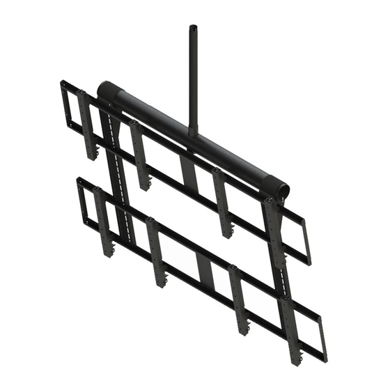
Installation and Assembly:
2 x 2 Video Wall Ceiling Mount for 40" - 55"
flat Panel Displays
Model: DS-VWT955-2X2
COMPATIBILITY
Display width must be a minimum of 36"
Display height must be a minimum of 20.875"
Screen width + horizontal mounting hole pattern must be less than 1745mm
For 200 mm vertical mounting patterns, screen height + mounting hole pattern must be ≤ 890 mm
For 300 mm vertical mounting patterns, screen height + mounting hole pattern must be ≤ 990 mm
For 400 mm vertical mounting patterns, screen height + mounting hole pattern must be ≤ 1090 mm
Maximum Load Capacity: 400 lb (181 kg); 100lb (45 kg) per screen
EXTENSION COLUMN
(SOLD SEPARATELY)
1 of 8
ISSUED: 01-23-12 SHEET #: 125-9278-5 03-06-14
Advertisement

Related Manuals for peerless-AV DS-VWT955-2X2


Summary of Contents for peerless-AV DS-VWT955-2X2
- Page 1 Installation and Assembly: 2 x 2 Video Wall Ceiling Mount for 40" - 55" flat Panel Displays Model: DS-VWT955-2X2 EXTENSION COLUMN (SOLD SEPARATELY) COMPATIBILITY Display width must be a minimum of 36" Display height must be a minimum of 20.875"...
-
Page 2: Parts List
Parts List Description Qty. Part # tilt bracket 145-1710 cross support tube 145-1708 end cap 590-1333 fiber washer 540-9432 retaining collar 1800-375 M8 x 16 mm phillips screw 520-9257 M5 x 8 mm phillips screw 570-0005 adapter bracket 145-1711 adapter support 145-1238 4 mm allen wrench 560-9646... - Page 3 Secure extension column (sold separately) to cross support (B) using retaining collar (E), fiber washer (D), and one M5 x 8 mm phillips screw (G). Restrict swivel using two M6 x 6 mm set screws (K). NOTE: Make sure that M5 x 8 mm phillips screw is positioned inside of notch of extension column as shown in detail 2.
- Page 4 Secure two M5 x 8 mm phillips screws (G) to ends of cross support tubes (B) as shown in detail 5. Detail 5 Attaching Adapter Brackets to Display NOTE: Make sure to use largest hole pattern on back of display. Attach adapter brackets (H) to back of display using four M6 x 12 mm socket pin screws (Q) or four M8 x 15 mm socket pin screws (P).
- Page 5 Determine position of horizontal rails (I) using the formula below. 1. Locate the position of the lower horizontal rail (I) and attach to tilt brackets (A). 2. Use display height to determine location of upper horizontal rail (I), NOTE: Lowest horizontal rail (D) position shown below. NOTE: Horizontal rails (D) must be secured using sixteen 1/4-20 hex head type-F screws (N, step 6).
-
Page 6: Safety Cable
Feed safety cable through extension column (sold separately). Run cable out of the bottom of the extension column (sold separately) and through openings in adapter supports (I) as shown below. Pull safety cable taught and secure using u-bolt to fasten the looped end to the cable as shown in detail 7. Wrap excess cable around the extension column (sold separately). -
Page 7: Security Screw
Hook adapter brackets (H) with displays onto adapter supports (I) as shown. Detail 9 Loosely fasten in place using security screw as shown in detail 10. DISPLAY NOT SHOWN FOR CLARITY SECURITY SCREW Detail 10 Adapter Bracket Adjustment Adapter brackets (H) can be adjusted horizontally as shown. Once adapter brackets (H) are in desired position secure using 4mm allen wrench (K) to lock in place. - Page 8 Adapter Bracket Adjustment Use legend below to determine position of display. NOTE: Each knob can be adjusted independently for fine tuning angle adjustments. Turn knobs CLOCKWISE to raise display height. Turn knobs CLOCKWISE to push out display. Turn knobs COUNTER-CLOCKWISE to lower display height. Turn knob COUNTER-CLOCKWISE to pull in display.
Need help?
Do you have a question about the DS-VWT955-2X2 and is the answer not in the manual?
Questions and answers