Advertisement
Quick Links
Advertisement

Related Manuals for peerless-AV DS-VWM770


Summary of Contents for peerless-AV DS-VWM770
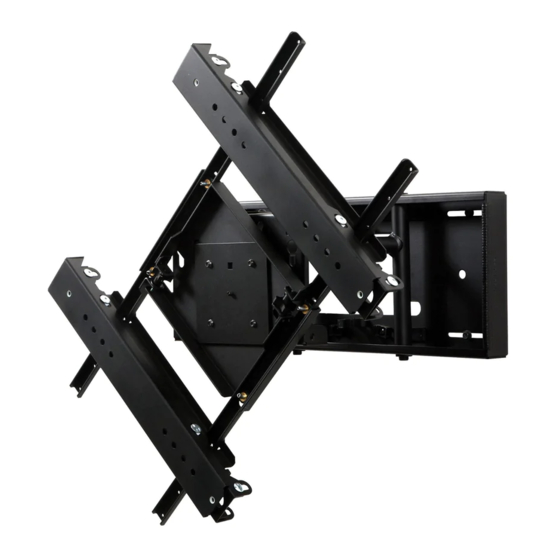
- Page 1 DS-VWM770 46" - 70" 125 lb (1168 - 1778 cm) (56 kg) 2013-08-27 #:125-9465-5 2014-04-21...
- Page 2 WARNING ENG - This product is designed to be installed on wood stud, solid concrete or cinder block walls. Hardware is included for wood stud, solid concrete and cinder block installation. Before installing make sure the supporting surface will support the combined load of the equipment and hardware. Screws must be tightly secured. Do not overtighten screws or damage can occur and product may fail.
- Page 3 Tools Needed for Assembly. ENG To properly tighten screws: Tighten until screw head makes contact, then tighten another 1/2 turn. Do not overtighten screws. +1/2 5/32" 5/16" (8mm) (4mm) 3/8" (10mm) 2013-08-27 #:125-9465-5 2014-04-21...
-
Page 4: Parts List
Parts (Before beginning, make sure you have all parts shown below). Parts List Part Description Qty. Part # wall plate 201-0387 concrete anchor 590-0320 wood screw 5S1-015-C03 locking tab 200-1871 .219" spacer 540-1032 polyester sleeve 600-1014 cable tie 560-9711 M5 x 10mm screw 520-1063 M4 x 12mm screw 510-1079... - Page 5 J (1) I (4) G (4) H (5) M5 x 40mm M4 x 12mm cable tie M5 x 10mm K (1) 4mm allen wrench L (2) N (4) P (4) O (4) M (1) adaptor bracket M10 x 15mm M5 x 8mm M6 x 12mm plate assembly Q (4)
- Page 6 Remove Wood stud wall. Concrete/Cinder block. 2a-1 Use stud finder to locate and mark stud center lines. WARNING ENG - When installing Peerless wall mounts on a wood stud wall covered with gypsum board (drywall), verify that the woods studs are a minimum of 2" x 4"...
- Page 7 2a-2 16.00" (406mm) Level wallplate. Mark mounting holes on stud centerlines (studs must be 16" (406mm) on center). 2a-3 2.5" (64mm) 5/32" 5/32" (4mm) (4mm) Drill mounting holes into supporting surface (2.5" (64mm) minimum depth required). Mounting hole must center on stud. 2a-4 Level wallplate.
- Page 8 WARNING ENG • When installing Peerless wall mounts on a concrete wall, the wall must be at least 8" thick with a minimum compressive strength of 2000 psi. • When installing Peerless wall mounts on a cinder block wall, the cinder blocks must meet ASTM C-90 specifications and have a minimum nominal width of 8".
- Page 9 2b-3 2b-3 Insert anchor flush to concrete. B (4) 1b-4 2b-4 Level wallplate. Install using concrete anchors and wood screws provided. Maximum 80 in. • lb (9 N.M.). C (4) 2013-08-27 #:125-9465-5 2014-04-21...
- Page 10 2013-08-27 #:125-9465-5 2014-04-21...
- Page 11 Setting the angle of the display. ENG The viewport is used to reveal notches indicating the angle (view) of the display. Rotating Plate Notch Viewport Line up the viewport with the desired angle (view). Viewport Rotating Plate Rotation Guide Portrait TOP OF TV PORTRAIT 90°...
- Page 12 Leaving ¼" exposed thread, thread two M10 x 15mm (N) screws through plate assembly (M) and rotating plate. 1/4" (6mm) Slide plate assembly (M) into adaptor bracket (L) slots. 2013-08-27 #:125-9465-5 2014-04-21...
- Page 13 Determine VESA mounting pattern. 300mm x 300mm 400mm x 400mm 400mm x 300mm 400mm x 200mm 500mm x 400mm 600mm x 400mm 2013-08-27 #:125-9465-5 2014-04-21...
- Page 14 P, R Secure plate assembly (M) to adaptor bracket (L) with four M5 x 8mm screws (O). Do not use screws on inner adaptor bracket opening. 2013-08-27 #:125-9465-5 2014-04-21...
- Page 15 Hook M10 x 15mm screws (N) of plate assembly (M) into top two key holes of wall plate (A). TIGHTEN CONNECTING HARDWARE 2013-08-27 #:125-9465-5 2014-04-21...
- Page 16 Display adjustment. 2013-08-27 #:125-9465-5 2014-04-21...
- Page 17 Use legend below to determine position of display. Each knob can be adjusted independently for fine tuning adjustments. Turn knob CLOCKWISE to move corner toward the wall. Turn knob COUNTER-CLOCKWISE to move corner away from the wall. 2013-08-27 #:125-9465-5 2014-04-21...
- Page 18 OPTIONAL: Alternative wall plate lock-down positions. 11-1 Lock-down in retracted position. J (1) 11-2 Lock-down one arm in place. H (1) D (1) E (1) 2013-08-27 #:125-9465-5 2014-04-21...
- Page 19 This page intentionally left blank. 2013-08-27 #:125-9465-5 2014-04-21...
-
Page 20: Limited Five-Year Warranty
Peerless product. ® This warranty gives specific legal rights, and you may also have other rights which vary from state to state. Patented. Utility Patent No. 8,517,322 Peerless-AV 2300 White Oak Circle Aurora, IL 60502 Email: tech@peerlessmounts.com Ph: (800) 865-2112 Fax: (800) 359-6500 www.peerless-av.com...
Need help?
Do you have a question about the DS-VWM770 and is the answer not in the manual?
Questions and answers