Advertisement
Installation and Assembly
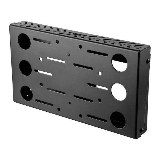
Model: DS509
Maximum Load Capacity:
200 lb (90.7 kg)
2300 White Oak Circle • Aurora, IL 60502 • (800) 865-2112 • Fax: (800) 359-6500 • www.peerlessmounts.com
os
For OSHPD installations,
please contact Peerless
Customer Service for a
copy of the OPA.
ISSUED: 04-06-09 SHEET #:125-9059-3 07-11-11
pd
Advertisement
Table of Contents

Related Manuals for peerless-AV DS509


Summary of Contents for peerless-AV DS509
- Page 1 Installation and Assembly Model: DS509 For OSHPD installations, please contact Peerless Customer Service for a copy of the OPA. Maximum Load Capacity: 200 lb (90.7 kg) 2300 White Oak Circle • Aurora, IL 60502 • (800) 865-2112 • Fax: (800) 359-6500 • www.peerlessmounts.com...
-
Page 2: Table Of Contents
IMPORTANT! Read instruction sheet before you start installation and assembly. WARNING • Do not begin to install your Peerless product until you have read and understood the instructions and warnings contained in this Installation Sheet. If you have any questions regarding any of the instructions or warnings, for US customers please call Peerless customer care at 1-800-865-2112, for all international customers, please contact your local distributor. -
Page 3: Parts List
Before you begin, make sure all parts shown are included with your product. Parts may appear slightly different than illustrated. Parts List Description Qty. Part # wall plate 145-1055 tilt plate 145-1053 #14 x 2.5" wood screw 5S1-015-C03 concrete anchor 590-0097 M8 x 15 mm socket pin screw 520-1068... -
Page 4: Installation To Double Wood Stud Wall
Installation to Double Wood Stud Wall WARNING • Installer must verify that the supporting surface will safely support the combined load of the equipment and all attached hardware and components. • Tighten wood screws so that wall plate is fi rmly attached, but do not overtighten. Overtightening can damage the screws, greatly reducing their holding power. -
Page 5: Installation To Solid Concrete Or Cinder Block
Installation to Solid Concrete or Cinder Block WARNING • When installing Peerless wall mounts on cinder block, verify that you have a minimum of 1-3/8" of actual concrete thickness in the hole to be used for the concrete anchors. Do not drill into mortar joints! Be sure to mount in a solid part of the block, generally 1"... -
Page 6: Installation To Metal Stud Wall
Installation to Metal Studs WARNING • Drywall must be 1/2" or thicker, and metal stud must be 24 gauge or thicker. • Make sure that the wall will safely support the combined load of the equipment and all attached hardware and components. - Page 7 Placement of Adhesive Strips Place adhesive strips (K) on the wall plate (A) in location that will allow the most contact with CPU. Note: Placement of adhesive strips will vary depending on size of CPU as shown in fi gure 2.2 fi...
-
Page 8: Attaching Tilt Plate To Screen
Attaching Adapter Plate to Screen fi g. 4.1 Attaching adapter plate to screen with VESA hole SCREEN pattern: Choose hole pattern and fasteners shown in detail 2 for mounting screen with VESA mounting patterns. Hand thread screws (F, G or H) through washers (J or P) and adapter plate (B) into screen as shown in fi... -
Page 9: Attaching Tilt Plate To Wall Plate
Attaching Adapter Plate to Wall Plate Thread two M8 x 15 mm screws (E) into bottom holes of wall plate (A) leaving 1/8" space between head of screw and wall plate as shown in fi gure 5.1. Guide hook slots of adapter plate (B) onto screws (E), while supporting weight of screen, align top holes of wall plate and adapter bracket to the desired tilt angle and secure with two M8 x 15 mm screws (E).
Need help?
Do you have a question about the DS509 and is the answer not in the manual?
Questions and answers