
Related Manuals for Shini SCM-E Series


Summary of Contents for Shini SCM-E Series
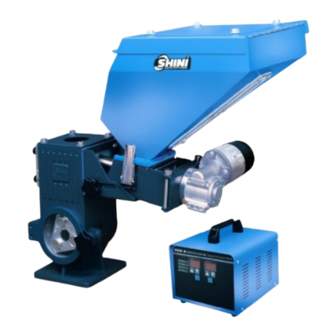
- Page 1 SCM-E series Volumetric Dosers Original Manual Instruction Date: Feb. 2012 Version: V4.2 (English)
-
Page 3: Table Of Contents
Contents General Description ..................7 1.1 Coding Principle ..................8 1.2 Feature....................8 1.3 Technical Specifications................ 10 1.3.1 Dimensions of Single-color Doser..........10 1.3.2 Dimensions of Two-color Doser..........11 1.3.3 Specification List................. 12 1.4 Safety Regulations ................13 1.4.1 Safety Signs and Labels ............. 13 1.5 Exemption Clause ................. - Page 4 3.3 Sockets and Main Switch at the Back of Control Box......31 Application and Operation................. 32 4.1 Operation Guide..................32 4.2 Control Panel ..................32 4.3 Start/stop of the Machine ..............33 4.4 Operation Guide..................33 4.5 Change Color Additives ................ 37 4.6 Replace Dosing Screws ................
- Page 5 Picture 2-1:Working Principle of Single-color Doser..........15 Picture 2-2:Working Principle of Two-color Doser..........16 Picture 2-3:Electrical Descriptions..............25 Picture 2-4:Electrical Cornponents Layout ............26 Picture 2-5:Main hopper..................28 Picture 2-6:Blending System................28 Picture 2-7:Floor Stand ..................29 Picture 3-1:Installation of Single-color Doser ............30 Picture 3-2:Installation of Two-color Doser ............30 Picture 3-3:Bi-chrome color machine's control cabinet ........31 Picture 4-1:Operation Guide ................32 Picture 4-2:Change Color Additives ..............37...
- Page 6 6(39)
-
Page 7: General Description
Please read this manual carefully before installation and using of the machine to prevent damage or personal injuries. The SCM-E series "Standard" volumetric dosers are suitable for auto-proportional mixing of new materials, regrinds, master batch and additives. A carbon-brush motor is used in this series. The operator controls the precise dosing screw by setting its rotation speed to extrude materials with an accuracy of ±1%. -
Page 8: Coding Principle
1.1 Coding Principle 1.2 Feature Standard configuration 1) Motor rotating speed and plasticizing time can be adjusted simply and directly. 2) High and low potential starts can be selected for IMM connecting signal 3) Fixed 60-second output testing. 4) Machine halts and sounds alarm when motor faults. 5) Use carbon brush motor, the carbon can be replaced at fixed period. - Page 9 Chapter 6, which contains service instructions intended for service engineers. Other chapters contain instructions for the daily operator. Any modifications of the machine must be approved by SHINI in order to avoid personal injury and damage to machine. We shall not be liable for any damage caused by unauthorized change of the machine.
-
Page 10: Technical Specifications
1.3 Technical Specifications 1.3.1 Dimensions of Single-color Doser 1.3.1.1 Dimensions of Single-color Doser Main Body Picture 1-1:Dimensions of Single-color Doser Main Body 1.3.1.2 Control Cabinet Picture 1-2:Dimensions of Single-color Doser Control Cabinet 10(39) -
Page 11: Dimensions Of Two-Color Doser
1.3.2 Dimensions of Two-color Doser 1.3.2.1 Dimensions of Two-color Doser Main Body Picture 1-3:Dimensions of Two-color Doser Main Body 1.3.2.2 Dimensions of Two-color Control Cabinet Picture 1-4:Dimensions of Two-color Control Cabinet 11(39) -
Page 12: Specification List
1.3.3 Specification List Table 1-1:Specification List Single Color Unit SCM-E Double Color Units SCM-E-D Model 38-16 38-14 38-12 75-16 75-14 75-12 38/38 38/75 75/75 Motor Power 0.06 0.06 0.06 0.06 0.06 0.06 0.06×2 0.06×2 0.06×2 (kW) (50/60Hz) Motor Speed 0~3000 0~3000 0~3000 0~3000... -
Page 13: Safety Regulations
The following statements clarify the responsibilities and regulations born by any buyer or user who purchases products and accessories from Shini (including employees and agents). Shini is exempted from liability for any costs, fees, claims and losses caused by reasons below: 13(39) - Page 14 3. Any operational actions that are not authorized by Shini upon machine, including adding or replacing accessories, dismantling, delivering or repairing.
-
Page 15: Structure Characteristics And Working Principle
Structure Characteristics and Working Principle 2.1 Main Functions The SCM-E series "Standard" volumetric dosers are suitable for auto-proportional mixing of new materials, regrinds, master batch and additives. A carbon-brush motor is used in this series. According to the set mixing proportion, the microprocessor accurately controls rotation of the high precise dosing screw to squeeze out materials with an accuracy of ±1%. -
Page 16: Working Principle Of Two-Color Doser
2.2.2 Working Principle of Two-color Doser Two-color doser combines two dosing units with a blending system. It can be used to convey two color additives at the same time. Choose different kinds of dosing units according to additive usage. Each dosing unit is controlled by separate system, suitable for accurate dosing of virgin material, regrind, materbatch or other additives. -
Page 17: Assembly Drawing And Parts List
2.3 Assembly Drawing and Parts List 2.3.1 Assembly Drawing of Single-color Doser Remarks: Please refer to material List 2.3.2 for specific explanation of the Arabic numbers in parts drawing. Picture 2-3:Assembly Drawing of Single-color Doser 17(39) -
Page 18: Parts List Of Single-Color Doser
2.3.2 Parts List of Single-color Doser Table 2-1:Parts List of Single-color Doser (SCM-E-38-16/14/12) Part number Name SCM-E-38-16 SCM-E-38-14 SCM-E-38-12 Knob B type M8×35 YR40083500000 YR40083500000 YR40083500000 Flat gasket 8 YW66081900000 YW66081900000 YW66081900000 Nut M8 YW64000800100 YW64000800100 YW64000800100 Base door Tempered glass YW70125000000 YW70125000000 YW70125000000... - Page 19 Part number Name SCM-E-38-16 SCM-E-38-14 SCM-E-38-12 Side fixed housing New snap hook adjustable YW02003000400 YW02003000400 YW02003000400 Body fixed bracket 1 Hex socket screw M5×10 YW61051000100 YW61051000100 YW61051000100 Screw shaft option 2 Screw shaft Ф12 Screw shaft Ф12 sleeve Cruciform screw M3×6 YW61030600100 YW61030600100 YW61030600100...
- Page 20 Table 2-2:Parts List of Single-color Doser (SCM-E-75-16/14/12) Part number Name SCM-E-75-16 SCM-E-75-14 SCM-E-75-12 Knob B typem8×35 YR40083500000 YR40083500000 YR40083500000 Flat gasket 8 YW66081900000 YW66081900000 YW66081900000 Nut M8 YW64000800100 YW64000800100 YW64000800100 Base door Tempered glass YW70125000000 YW70125000000 YW70125000000 Spring of magnetic base YW01005000100 YW01005000100 YW01005000100...
- Page 21 Part number Name SCM-E-75-16 SCM-E-75-14 SCM-E-75-12 Side fixed housing New snap hook adjustable YW02003000400 YW02003000400 YW02003000400 Body fixed bracket 1 Hex socket screw m5×10 YW61051000100 YW61051000100 YW61051000100 Screw shaft option 2 Screw shaft ф12 Screw shaft ф12 sleeve Cruciform screw m3×6 YW61030600100 YW61030600100 YW61030600100...
-
Page 22: Assembly Drawing Of Two-Color Doser
2.3.3 Assembly Drawing of Two-color Doser Remarks: Please refer to material List 2.3.4 for specific explanation of the Arabic numbers in parts drawing. Picture 2-3:Assembly Drawing of Two-color Doser 22(39) -
Page 23: Parts List Of Two-Color Doser
2.3.4 Parts List of Two-color Doser Table 2-3:Parts List of Two-color Doser (SCM-E-D-38-16/14/12) Part number Name SCM-E-D-38/38 SCM-E -D-38/75 SCM-E -D-75/75 Knob B type m8×45 Flat gasket 8 YW66081900000 YW66081900000 YW66081900000 Nut M8 YW64000800100 YW64000800100 YW64000800100 Base door Tempered glass** YW70125000000 YW70125000000 YW70125000000... - Page 24 Part number Name SCM-E-D-38/38 SCM-E -D-38/75 SCM-E -D-75/75 Convey pipeline Nsk bearing 6003 YW11600300000 YW11600300000 YW11600300000 Material shutter Side fixed housing New snap hook adjustable YW02003000400 YW02003000400 YW02003000400 Body fixed bracket 1 Cruciform screw m5×10 YW61051000100 YW61051000100 YW61051000100 Screw shaft option 2 Screw shaft ф16 Cruciform screw m3×6 YW61030600100...
-
Page 25: Electrical Circuit Descriptions
2.4 Electrical Circuit Descriptions 2.4.1 Electrical Descriptions Picture 2-3:Electrical Descriptions 25(39) -
Page 26: Electrical Cornponents Layout
2.4.2 Electrical Cornponents Layout Picture 2-4:Electrical Cornponents Layout 26(39) -
Page 27: Bill Of Electrical Components
2.4.3 Bill of Electrical Components Table 2-4:Bill of Electrical Components Symbol Name Specifications Part number 24VDC YE80112200000 YE46201500000 Fuse** 5A Fuse YE46630500200 Switch 250V 16A 4P(WH) YE10210400000 Buzzer 24VDC YE84002700000 DC Power IN=175/240V OUT=24VDC 3.8A YE71102400000 Power line 250V~10A 3P YE51802300000 Socket YE68025300400... -
Page 28: Optional Accessories
2.5 Optional Accessories 2.5.1 Main hopper Single color doser can select main material hopper on customer demand. Picture 2-5:Main hopper 2.5.2 Blending System (for single-color doser) Picture 2-6:Blending System 28(39) -
Page 29: Floor Stand
2.5.3 Floor Stand When customer needs work with SHD-100~300kg or SHD-16OU~450U dryer choose this type floor stand. Picture 2-7:Floor Stand 29(39) -
Page 30: Installation And Debugging
Installation and Debugging Read this chapter carefully before installation. Install the machine by following steps. Power supply of the machine should be done by qualified electricians! 3.1 Install on Extrusion or Injection Moulding Machine Picture 3-1:Installation of Single-color Doser Picture 3-2:Installation of Two-color Doser According to the specifications of mounting holes on the extruder or injection moulding machine, drill 4 screw holes on the base of SCM machine. -
Page 31: Sockets And Main Switch At The Back Of Control Box
3.3 Sockets and Main Switch at the Back of Control Box Name of parts: 1. Motor wire socket 2. Main power socket 3. Connect to signal circuit of injection moulding machine or extruder 4. System switch 5. Buzzer 6. Fuse 7. -
Page 32: Application And Operation
Application and Operation 4.1 Operation Guide Picture 4-1:Operation Guide 4.2 Control Panel Item Functions Remarks This indicator shines Power light when power is connected. This indicator shines if there is no plasticizing It indicates the phase of waiting signal Stand-by light signal of IMM or starting. -
Page 33: Start/Stop Of The Machine
Item Functions Remarks It is used to display the Motor rotating setting value of motor speed setting rotating speed. Up-regulator of Increase motor rotate Highest rotate speed 999 rotate speed. speed. Down-regulator Decrease motor rotate of rotate Lowest rotate speed 30 speed. - Page 34 Kg/Hr) stands for the total weight of IMM each module finished goods and sprues. P stands for the percentage of color masterbatch. T stands for the plasticizing time. (Unit: second)) Method of calculation for extruder: ×P stands for the color masterbatch quantity demanded per hour of extruder. (Unit: Kg/Hr) stands for the actual production capacity per hour of IMM or extruder.
- Page 35 Setting of motor rotate speed based on Sp value: if that is the applied IMM mode, press clock key for over 3 seconds to start function of plasticizing time and set the time; if that is the applied extruder mode, it is no need to set plasticizing time and no display of plasticizing time showed on LED.
- Page 36 Table 4-1:Table of 50 Seconds Test Values 50 seconds test for the screw of SCM38 Color additives Screw diameter(mm) Weight(g) Φ12 131.6 White color additives 7028B, density 1.6. Φ2~3mm Φ14 228.2 particles, well-proportioned. Φ16 456.3 Φ12 White color additives 7018, density 1.4, Φ2~3mm Φ14 particles, well-proportioned.
-
Page 37: Change Color Additives
4.5 Change Color Additives 1) Loosen snap hook of hopper, draw out the hopper and screw. Then use high-pressure air to blow away the remained materials. 2) Add color additives. Picture 4-2:Change Color Additives 4.6 Replace Dosing Screws 1. Cut off power supply, loosen snap hook of hopper, and draw out the hopper and screw. -
Page 38: Trouble-Shooting
Trouble-shooting Failures Possible reasons Solutions 1. Power supply not connected. 1. Connect through power supply. No indicates on the 2. Fuse burnt out or control control cabinet. 2. Replace the fuse or control board. board problems. 1. Parameter mistakes 1. Reset parameters 2. -
Page 39: Maintenance And Repair
Maintenance and Repair 6.1 Service All the repair work should be done by qualified technicians to avoid personal injuries or damage of the machine. 6.2 Maintenance Please keep the surface of the machine free from pollutants. 6.3 Maintenance Schedule the Machine 6.3.1 About Model Manufacture date...
Need help?
Do you have a question about the SCM-E Series and is the answer not in the manual?
Questions and answers