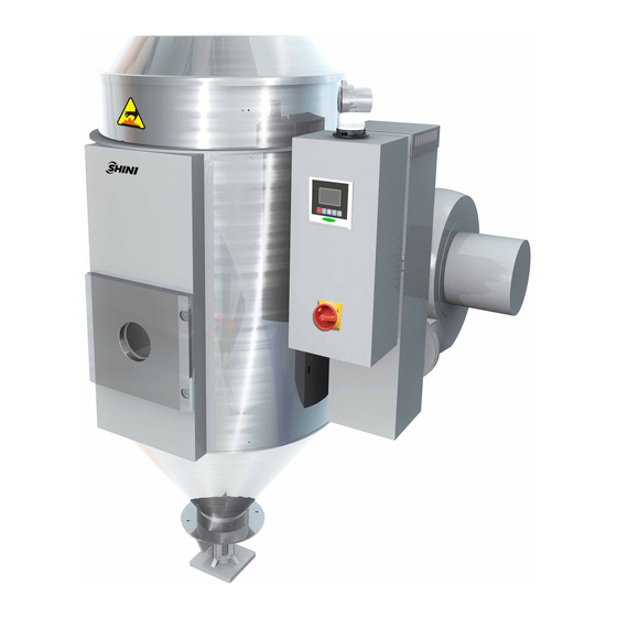
Shini SHD Product And Maintenance Manual
Hide thumbs Also See for SHD:
Table of Contents

Advertisement

Quick Links

Issued by department:
Date:
Shini/CSC-TM 2013-11
Catalog:
SHINI PRODUCTS&MAINTENANCE MANUAL
template:Standard_CN.dot; filename: Shini product repair manual; Printdate: 8/1/2014 1:58:00 PM; savedate: 8/1/2014 1:58:00 PM
Shini Group
Language:
Document Name:
zh-cn
Shini product repair manual.doc
Data:2014-08
Version:V1.1
Technology & Marketing Dept
Revision:
Page:
1.0
1 (62)

Advertisement

Table of Contents
loading
Need help?

Need help?

Do you have a question about the SHD and is the answer not in the manual?

Questions and answers

Summary of Contents for Shini SHD

  • Page 1 Technology & Marketing Dept Issued by department: Date: Language: Document Name: Revision: Page: Shini/CSC-TM 2013-11 zh-cn Shini product repair manual.doc 1 (62) Catalog: SHINI PRODUCTS&MAINTENANCE MANUAL Data:2014-08 Version:V1.1 template:Standard_CN.dot; filename: Shini product repair manual; Printdate: 8/1/2014 1:58:00 PM; savedate: 8/1/2014 1:58:00 PM...
  • Page 2: Table Of Contents

    4.4.7 Memory Error E-08 ................16 4.4.8 Honeycomb-rotor Fault Alarm............16 4.4.9 Actual temperature exceeds EGO setpoint—Over-temperature alarm E-10 16 4.4.10 Thermocouple Polarity False Alarm E-11 ..........16 4.4.11 PID Self-tuning Wrong E-12...............16 template:Standard_CN.dot; filename: Shini product repair manual; Printdate: 8/1/2014 1:58:00 PM; savedate: 8/1/2014 1:58:00 PM...
  • Page 3 10. Capacitive Proximity Switch Adjustment ............29 10.1 Products Information ..................29 10.2 Working Principle ..................29 10.3 KI5082-BVKG Adjustment................29 10.4 KI0020-BBOA adjustment ................30 11. SCR Crystallization and Unloading Abnormal ..........31 template:Standard_CN.dot; filename: Shini product repair manual; Printdate: 8/1/2014 1:58:00 PM; savedate: 8/1/2014 1:58:00 PM...
  • Page 4 19.1 Products Information ..................56 19.2 Applicable Models ..................56 19.3 Adjustment Method ..................56 20. TP Series Turbopump ..................58 20.1 Applicable Models ..................58 20.2 Products Information ..................58 20.3 Working principle..................58 template:Standard_CN.dot; filename: Shini product repair manual; Printdate: 8/1/2014 1:58:00 PM; savedate: 8/1/2014 1:58:00 PM...
  • Page 5 Technology & Marketing Dept Issued by department: Date: Language: Document Name: Revision: Page: Shini/CSC-TM 2013-11 zh-cn Shini product repair manual.doc 5 (62) Catalog: 20.4 Replacing Shaft Seal..................58 template:Standard_CN.dot; filename: Shini product repair manual; Printdate: 8/1/2014 1:58:00 PM; savedate: 8/1/2014 1:58:00 PM...
  • Page 6: Introduction

    If you wish to learn more about related products, you can use the following three methods to contact us: China service hotline:800-999-3222 SHINI group website:www.shini.com Fax:(886)769-83313589 template:Standard_CN.dot; filename: Shini product repair manual; Printdate: 8/1/2014 1:58:00 PM; savedate: 8/1/2014 1:58:00 PM...
  • Page 7: Heating Pipe

    Heating pipe must be replaced with the same specifications, adaptable voltage and power in order to achieve the original heating effect. If not, it will cause heating pipe template:Standard_CN.dot; filename: Shini product repair manual; Printdate: 8/1/2014 1:58:00 PM; savedate: 8/1/2014 1:58:00 PM...
  • Page 8 4.4kw,much lower than the nominal value of 12kw. If the heating pipe is used for 460v(the same wiring),its actual power is about 17.6kw,much higher than the nominal value of 12kw. template:Standard_CN.dot; filename: Shini product repair manual; Printdate: 8/1/2014 1:58:00 PM; savedate: 8/1/2014 1:58:00 PM...
  • Page 9: Dewpoint Detection Device

    3.4 Installation and Commissioning Dewpoint sensor includes a transmitter body and a M12 connector, Its definition of each pin and wiring as follows: Pic 3-2 Dewpoint transmitter pin template:Standard_CN.dot; filename: Shini product repair manual; Printdate: 8/1/2014 1:58:00 PM; savedate: 8/1/2014 1:58:00 PM...
  • Page 10: Alarm Exclusion

    Dewpoint monitor lid connect with body through hidden discount. When the lid is removed, just pull the side of lid to the outside, you can remove the lid. template:Standard_CN.dot; filename: Shini product repair manual; Printdate: 8/1/2014 1:58:00 PM; savedate: 8/1/2014 1:58:00 PM...
  • Page 11: How To Set Parameters

    Average filter value F-02 Sampling time ℃ F-03 Unit selection F-04 Offset compensation F-05 20mA input value F-06 4mA input value F-07 Maximum display F-08 Minimum display template:Standard_CN.dot; filename: Shini product repair manual; Printdate: 8/1/2014 1:58:00 PM; savedate: 8/1/2014 1:58:00 PM...
  • Page 12: Temperature Controller Tu-01

    LED digital display area shows the fault code. After the alarm occurs, you need to check whether temperature line is disconnected first, if not the controller can be judged abnormal. template:Standard_CN.dot; filename: Shini product repair manual; Printdate: 8/1/2014 1:58:00 PM; savedate: 8/1/2014 1:58:00 PM...
  • Page 13: Anti-Phase Alarm E-02

    Blower air inlet filter is clogged serious. Seriously clogged filter will result in reduced air flow into the high-pressure blower, the corresponding increase in its template:Standard_CN.dot; filename: Shini product repair manual; Printdate: 8/1/2014 1:58:00 PM; savedate: 8/1/2014 1:58:00 PM...
  • Page 14: Actual Temperature Exceeds The Maximum Temperature-Over Heat

    PID parameters for controlling temperature heat method, if the parameters are not correct, will cause heating system heat abnormally. 4.4.5 Actual temperature exceeds the maximum temperature—Over heat alarm E-05 template:Standard_CN.dot; filename: Shini product repair manual; Printdate: 8/1/2014 1:58:00 PM; savedate: 8/1/2014 1:58:00 PM...
  • Page 15: Actual Temperature Is Higher Than The Sum Of Set Temperature And Alarm Temperature-Over-Temperature Alarm E-07

    Confirm microcomputer panel internal parameters are correct. Microcomputer panel internal save the PID parameters for controlling temperature heat method, if the parameters are not correct, will cause heating system heat abnormally. To template:Standard_CN.dot; filename: Shini product repair manual; Printdate: 8/1/2014 1:58:00 PM; savedate: 8/1/2014 1:58:00 PM...
  • Page 16: Memory Error E-08

    Now you can reboot and start PID auto-tuning, or manually enter the PID parameters to exclude fault. template:Standard_CN.dot; filename: Shini product repair manual; Printdate: 8/1/2014 1:58:00 PM; savedate: 8/1/2014 1:58:00 PM...
  • Page 17: Honeycomb-Rotor Maintenance

    Long life honeycomb-rotor, can be cleaned repeatedly, easy template:Standard_CN.dot; filename: Shini product repair manual; Printdate: 8/1/2014 1:58:00 PM; savedate: 8/1/2014 1:58:00 PM...
  • Page 18: Daily Maintenance

    If the air is too dry, try using humidistat to increase humidity, the step requires 1 hour. template:Standard_CN.dot; filename: Shini product repair manual; Printdate: 8/1/2014 1:58:00 PM; savedate: 8/1/2014 1:58:00 PM...
  • Page 19: Honeycomb-Rotor Deterioration Phenomenon

    Chemical reaction will destroy the adsorbent pores crystals such as dilute acid or alkali gases will cause silica and zeolites crystalline and amorphous material damage. template:Standard_CN.dot; filename: Shini product repair manual; Printdate: 8/1/2014 1:58:00 PM; savedate: 8/1/2014 1:58:00 PM...
  • Page 20: Hr Timer(Panasonic 24Hr A-Tb-72-D 230V/50Hz/60Hz

    As shown in above figure, the machine began to work at 8:00 until 16:00, the machine stops, and every day cycle. template:Standard_CN.dot; filename: Shini product repair manual; Printdate: 8/1/2014 1:58:00 PM; savedate: 8/1/2014 1:58:00 PM...
  • Page 21: Temperature-Controlled Meter Shini(0-199℃)

    Temperature control panel lights instruction follows ON/OFF:ON state is bright green, OFF state is bright red; AL: Lights indicates over-temperature alarm output; TC B:Lights indicates thermocouple break. template:Standard_CN.dot; filename: Shini product repair manual; Printdate: 8/1/2014 1:58:00 PM; savedate: 8/1/2014 1:58:00 PM...
  • Page 22: Cleaning Coolers

    5. Place cooler in a cool and dry place for 4 hours, until the silicone dry, replace the cooler and connect the machine to pipe. template:Standard_CN.dot; filename: Shini product repair manual; Printdate: 8/1/2014 1:58:00 PM; savedate: 8/1/2014 1:58:00 PM...
  • Page 23: Dewpoint Temperature Exceeds

    View the thermometer value on cooler, if it is higher than 35 ℃, the cooler must be connected to a lower temperature cooling water; Pic 9-2 template:Standard_CN.dot; filename: Shini product repair manual; Printdate: 8/1/2014 1:58:00 PM; savedate: 8/1/2014 1:58:00 PM...
  • Page 24: Regeneration Temperature Is Set Incorrectly

    If the honeycomb material is silicone, the regeneration temperature is set to 150 ℃; If honeycomb material is molecular sieve, regeneration temperature should be set to 180℃. Pic 9-3 template:Standard_CN.dot; filename: Shini product repair manual; Printdate: 8/1/2014 1:58:00 PM; savedate: 8/1/2014 1:58:00 PM...
  • Page 25: Honeycomb-Rotor Blocking

    Use compressed air to clean the lid and filter; Use a rag to air filter barrel wall; After cleaning, install filter in reverse order. Pic 9-5 template:Standard_CN.dot; filename: Shini product repair manual; Printdate: 8/1/2014 1:58:00 PM; savedate: 8/1/2014 1:58:00 PM...
  • Page 26: Drying Capacity Insufficient

    70~100 0.65 2.0 ~2.4 0.65 95~110 1.7~2.4 0.35 1.8 ~2.4 0.46 110~125 1.8~2.1 140~150 1.5~1.8 0.28 120~170 0.65 1.8~2.0 0.31 80~90 2.5~2.8 1.7~2.1 1.7~2.1 0.32 1.7~2.1 template:Standard_CN.dot; filename: Shini product repair manual; Printdate: 8/1/2014 1:58:00 PM; savedate: 8/1/2014 1:58:00 PM...
  • Page 27 1、Drying air volume has considered equipment air volume margin: 2、The above data is only for reference when equipment select, n practical application, please refer to the parameter which is provided by raw material suppliers. template:Standard_CN.dot; filename: Shini product repair manual; Printdate: 8/1/2014 1:58:00 PM; savedate: 8/1/2014 1:58:00 PM...
  • Page 28: Heat Duct Leak

    Hand to feel if honeycomb upper and lower lid silicone seal around the obvious leak, if so, you need to replace the silicone seals. Pic 9-6 template:Standard_CN.dot; filename: Shini product repair manual; Printdate: 8/1/2014 1:58:00 PM; savedate: 8/1/2014 1:58:00 PM...
  • Page 29: Capacitive Proximity Switch Adjustment

    3. If the above-mentioned state can not be adjusted, please check whether the wire is connected securely, or replace with a new proximity switch.(note: black wire—signal wire; white wire—no connection; blue wire—connect to 24V-; brown wire—24V+) template:Standard_CN.dot; filename: Shini product repair manual; Printdate: 8/1/2014 1:58:00 PM; savedate: 8/1/2014 1:58:00 PM...
  • Page 30: Ki0020-Bboa Adjustment

    V-, brown wire—connect to V+) 5. The gap between the proximity switch and the barrel wall should be adjusted in 3 ~ 6mm, no more than 8mm. template:Standard_CN.dot; filename: Shini product repair manual; Printdate: 8/1/2014 1:58:00 PM; savedate: 8/1/2014 1:58:00 PM...
  • Page 31: Scr Crystallization And Unloading Abnormal

    5 to switch to AL-1, set the value to 0; press button 5 to switch to AL-2, set the value to -22, press button 6 for at least 1 seconds to return run menu. template:Standard_CN.dot; filename: Shini product repair manual; Printdate: 8/1/2014 1:58:00 PM; savedate: 8/1/2014 1:58:00 PM...
  • Page 32 Set air outlet temperature: In run menu, set air outlet temperature to 93℃ through button 7 and button 8, If air outlet temperature of crystallization barrel reach 93℃, automatically output crystalline material. template:Standard_CN.dot; filename: Shini product repair manual; Printdate: 8/1/2014 1:58:00 PM; savedate: 8/1/2014 1:58:00 PM...
  • Page 33: Ac Contactor

    图 12-1 12.2 Check for Damage Pic 12-2 L1、L2、L3-Power fire wire 1-Auxiliary contact 2-Contact of voltage input template:Standard_CN.dot; filename: Shini product repair manual; Printdate: 8/1/2014 1:58:00 PM; savedate: 8/1/2014 1:58:00 PM...
  • Page 34 After contactor actuates, resistance value is 0 between two points of auxiliary contacts marked as “NO”, resistance is infinite between two points of auxiliary contacts marked as “NC”, and vice versa. template:Standard_CN.dot; filename: Shini product repair manual; Printdate: 8/1/2014 1:58:00 PM; savedate: 8/1/2014 1:58:00 PM...
  • Page 35: Check Microswitch

    0, indicating microswitch is broken and need to replace a new one. template:Standard_CN.dot; filename: Shini product repair manual; Printdate: 8/1/2014 1:58:00 PM; savedate: 8/1/2014 1:58:00 PM...
  • Page 36: Check Magic Eye Switch

    4. When foreign body between transmitter and receiver cut off infrared, the resistance should be infinite, if it is 0, indicating magic eye switch has been damaged and need to replace a new one. template:Standard_CN.dot; filename: Shini product repair manual; Printdate: 8/1/2014 1:58:00 PM; savedate: 8/1/2014 1:58:00 PM...
  • Page 37: Check Magnetic Reed Switch

    0, you need to replace a new one. template:Standard_CN.dot; filename: Shini product repair manual; Printdate: 8/1/2014 1:58:00 PM; savedate: 8/1/2014 1:58:00 PM...
  • Page 38: Replace Carbon Brush

    (Be careful not to overexert prevent deformation fracture upside down), then remove the protective cover up. As shown in the figure below. template:Standard_CN.dot; filename: Shini product repair manual; Printdate: 8/1/2014 1:58:00 PM; savedate: 8/1/2014 1:58:00 PM...
  • Page 39 4. After removing the protective cover, as shown below, loosen the screws, remove the carbon brush plate. Pic 16-3 5. As shown, use a screwdriver to pry the insert some gaps. template:Standard_CN.dot; filename: Shini product repair manual; Printdate: 8/1/2014 1:58:00 PM; savedate: 8/1/2014 1:58:00 PM...
  • Page 40 Pic 16-4 6. Use a screwdriver to block the gaps which is pried, screwdriver rotate in the direction of the arrow, Loosen the inserts. Pic 16-5 template:Standard_CN.dot; filename: Shini product repair manual; Printdate: 8/1/2014 1:58:00 PM; savedate: 8/1/2014 1:58:00 PM...
  • Page 41 7. Loosen the inserts (Arrow 1 in figure), remove the carbon brush (Arrow 2 in figure), and replace a new one. Note the small bump (Arrow 3) in the bottom of brush must block bracket recess (Arrow 4). Pic 16-6 template:Standard_CN.dot; filename: Shini product repair manual; Printdate: 8/1/2014 1:58:00 PM; savedate: 8/1/2014 1:58:00 PM...
  • Page 42 Shini/CSC-TM 2013-11 zh-cn Shini product repair manual.doc 42 (62) Catalog: 8. Insert male tab into carbon brush. Pic 16-7 9. Put plate, tighten the screws. Pic 16-8 template:Standard_CN.dot; filename: Shini product repair manual; Printdate: 8/1/2014 1:58:00 PM; savedate: 8/1/2014 1:58:00 PM...
  • Page 43 10. Lead wire pull up (to prevent wire block), and press down with two thumbs in the same time, four buckle must have fastened. Pic 16-9 11. Use a screwdriver to push the ends of the reed in place. Pic 16-10 template:Standard_CN.dot; filename: Shini product repair manual; Printdate: 8/1/2014 1:58:00 PM; savedate: 8/1/2014 1:58:00 PM...
  • Page 44: Carbon Brush Motor Model 119656-00

    (be careful not to use too much force to prevent buckle deformation fracture), then remove the protective cover up. As shown in the figure below. Pic 16-12 template:Standard_CN.dot; filename: Shini product repair manual; Printdate: 8/1/2014 1:58:00 PM; savedate: 8/1/2014 1:58:00 PM...
  • Page 45 4. After remove the protective cover, as shown in the figure below, loosen the screws and remove the brush plate. Pic 16-13 As shown, use a screwdriver to pry the insert some gaps Pic 16-14 template:Standard_CN.dot; filename: Shini product repair manual; Printdate: 8/1/2014 1:58:00 PM; savedate: 8/1/2014 1:58:00 PM...
  • Page 46 46 (62) Catalog: 6. Use a screwdriver to block the gaps which is pried, screwdriver rotate in the direction of the arrow, Loosen the inserts. Pic 16-15 template:Standard_CN.dot; filename: Shini product repair manual; Printdate: 8/1/2014 1:58:00 PM; savedate: 8/1/2014 1:58:00 PM...
  • Page 47 7. Loosen the inserts (Arrow 1 in figure), remove the carbon brush (Arrow 2 in figure), and replace a new one. Note the small bump (Arrow 3) in the bottom of brush must block bracket recess (Arrow 4). Pic 16-16 template:Standard_CN.dot; filename: Shini product repair manual; Printdate: 8/1/2014 1:58:00 PM; savedate: 8/1/2014 1:58:00 PM...
  • Page 48 Shini/CSC-TM 2013-11 zh-cn Shini product repair manual.doc 48 (62) Catalog: 8. Insert male tab into carbon brush. Pic 16-17 9. Put plate, tighten the screws. Pic 16-18 template:Standard_CN.dot; filename: Shini product repair manual; Printdate: 8/1/2014 1:58:00 PM; savedate: 8/1/2014 1:58:00 PM...
  • Page 49 10. Lead wire pull up (to prevent wire block), and press down with two thumbs in the same time, four buckle must have fastened. Pic 16-19 11. Use a screwdriver to push the ends of the reed in place. Pic 16-20 template:Standard_CN.dot; filename: Shini product repair manual; Printdate: 8/1/2014 1:58:00 PM; savedate: 8/1/2014 1:58:00 PM...
  • Page 50: Carbon Brush Motor Model 122255-00

    3. Remove the carbon brush (Arrow 1 in figure), and replace a new one. Note the small bump (Arrow 2) in the bottom of brush must block bracket recess (Arrow 3). Pic 16-22 template:Standard_CN.dot; filename: Shini product repair manual; Printdate: 8/1/2014 1:58:00 PM; savedate: 8/1/2014 1:58:00 PM...
  • Page 51 Issued by department: Date: Language: Document Name: Revision: Page: Shini/CSC-TM 2013-11 zh-cn Shini product repair manual.doc 51 (62) Catalog: 4. Tighten the screws, replace complete. 图 16-23 template:Standard_CN.dot; filename: Shini product repair manual; Printdate: 8/1/2014 1:58:00 PM; savedate: 8/1/2014 1:58:00 PM...
  • Page 52: Scm

    Note: The two methods above are empirical methods, it can only be “properly” adjusted according to the actual situation, and there is no specific adjustment value or adjustment range. template:Standard_CN.dot; filename: Shini product repair manual; Printdate: 8/1/2014 1:58:00 PM; savedate: 8/1/2014 1:58:00 PM...
  • Page 53: Injection/ Extruder Mode Wiring Changing

    24VDC), and CN-INJ pin 2 is connected to the positive of injection machines melt signal. 2) Shorten pin 1 and pin 2 of J3. Pic 17-1 template:Standard_CN.dot; filename: Shini product repair manual; Printdate: 8/1/2014 1:58:00 PM; savedate: 8/1/2014 1:58:00 PM...
  • Page 54 3) CN-Press2 pin 1 is connected to the negative of extruder speed signal (0~10VDC), and CN-INJ pin 2 is connected to the positive of extruder speed signal. Pic 17-2 template:Standard_CN.dot; filename: Shini product repair manual; Printdate: 8/1/2014 1:58:00 PM; savedate: 8/1/2014 1:58:00 PM...
  • Page 55: Thermal Expansion Valve Opening Adjustment

    1 above; to reduce the degree of opening of the expansion valve, rotate the knob clockwise, as shown in the figure 2 above. template:Standard_CN.dot; filename: Shini product repair manual; Printdate: 8/1/2014 1:58:00 PM; savedate: 8/1/2014 1:58:00 PM...
  • Page 56: Pressure Controller

    Adjustment method: Use cross-screwdriver to rotate adjustment screw to desired scale value. Clockwise to get smaller scale value, counter-clockwise to get larger scale value. template:Standard_CN.dot; filename: Shini product repair manual; Printdate: 8/1/2014 1:58:00 PM; savedate: 8/1/2014 1:58:00 PM...
  • Page 57 When the pressure drops to 5-1=4bar, pressure controller contacts switch; when the pressure rises to 5bar, pressure controller contacts switch. How to switch depends on the connection is normally open or normally closed contacts. template:Standard_CN.dot; filename: Shini product repair manual; Printdate: 8/1/2014 1:58:00 PM; savedate: 8/1/2014 1:58:00 PM...
  • Page 58: Tp Series Turbopump

    1) Use a brush to apply clean lubricant to bearing seal position, as shown in the figure below. Pic 20-1 template:Standard_CN.dot; filename: Shini product repair manual; Printdate: 8/1/2014 1:58:00 PM; savedate: 8/1/2014 1:58:00 PM...
  • Page 59 Pic 20-2 3) Flatten into place with tooling, use tina water moistened cloth clean the seal surface, as shown in the figure below. Pic 20-3 template:Standard_CN.dot; filename: Shini product repair manual; Printdate: 8/1/2014 1:58:00 PM; savedate: 8/1/2014 1:58:00 PM...
  • Page 60 5) Use a brush to apply clean lubricant to seal edge, mount pump shaft seal ring, and check for damage and other problem, as shown in the figure below. Pic 20-5 template:Standard_CN.dot; filename: Shini product repair manual; Printdate: 8/1/2014 1:58:00 PM; savedate: 8/1/2014 1:58:00 PM...
  • Page 61 (note: Protruding end of the spring must be installed into the seal gaps in the alignment), as shown in the figure below. Pic 20-7 template:Standard_CN.dot; filename: Shini product repair manual; Printdate: 8/1/2014 1:58:00 PM; savedate: 8/1/2014 1:58:00 PM...
  • Page 62 A type shaft circlip is fully engaged into motor circlip groove, as shown in the figure below. Pic 20-9 template:Standard_CN.dot; filename: Shini product repair manual; Printdate: 8/1/2014 1:58:00 PM; savedate: 8/1/2014 1:58:00 PM...

This manual is also suitable for:

SdlShd-uSdl-uSd-hScdSdd

Table of Contents