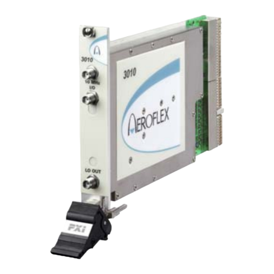
Aeroflex 3010 Series User Manual

Aeroflex 3010 Series User Manual

Rf synthesizer pxi modules
Hide thumbs Also See for 3010 Series:

Advertisement

Quick Links

sales@artisantg.com
artisantg.com
(217) 352-9330 |
|
Click HERE
Find the Cobham / Aeroflex 3010 at our website:

Advertisement

Table of Contents
loading
Need help?

Need help?

Do you have a question about the 3010 Series and is the answer not in the manual?

Questions and answers

Summary of Contents for Aeroflex 3010 Series

  • Page 1 (217) 352-9330 | Click HERE Find the Cobham / Aeroflex 3010 at our website:...
  • Page 2 3010 and 3011 (3010 Series) RF Synthesizer PXI Modules User Manual Document no. 46892/637 Issue 14 20 March 2013 Artisan Technology Group - Quality Instrumentation ... Guaranteed | (888) 88-SOURCE | www.artisantg.com...
  • Page 3: About This Manual

    Associated documentation)) explain how to set up and configure a 3010 Series RF synthesizer with a 3020 Series RF signal generator module or a 3030 Series RF digitizer module. Using the soft front panels and/or dll or COM object supplied, the modules form instruments that provide the functionality and performance of integrated, highly-specified signal generators or digitizers, but with the adaptability to satisfy a diverse range of test or measurement requirements.
  • Page 4: Intended Audience

    To maintain optimum performance, 3000 Series PXI modules should be used either with the software driver version with which they were supplied, or the latest driver, which you can download from the Aeroflex website. Aeroflex endeavours to ensure modules remain backwards compatible with earlier driver version releases.
  • Page 5: Associated Documentation

    Aeroflex website here. ® is a registered trademark of Aeroflex International Inc. in the US PXI™ is a trademark of the PXI Systems Alliance Windows®, Windows XP®, Windows® 7 and Windows NT® are registered trademarks of Microsoft Corporation Artisan Technology Group - Quality Instrumentation ...
  • Page 6: Patent Protection

    PREFACE Preface Patent protection The 3010 Series RF Synthesizer PXI module is protected by the following patents: GB 2294599 US 5781600 4609881 0125790 The PXI concept VXI and GPIB systems meet the specific needs of instrumentation users but are often too large and expensive for mainstream applications.
  • Page 7: General Information

    GENERAL INFORMATION Introduction This is the user manual for the 3010 and 3011 (‘3010 Series’) RF Synthesizer PXI modules. These high-performance frequency synthesizers: • cover the frequency range 1.5 GHz to 3.0 GHz with 1 Hz resolution. • use a single-width 3U module to provide the noise performance and frequency agility of conventional rack instruments.
  • Page 8: Deliverable Items

    GENERAL INFORMATION Software The 3010/3011 are supplied with a VXI PNP driver and soft front panel, and a dll, a COM object, and a .net assembly that provide similar functionality to the driver. PXI Studio 2, also supplied with the module, configures your PXI modules as logical instruments using an intuitive and powerful graphical interface.
  • Page 9: Putting Into Storage

    For the latest specifications, see the data sheet included on the CD-ROM (part no. 46886/028) or go to the Aeroflex website. All 3010 Series specifications are defined when used in conjunction with the driver software supplied with the module. Warm-up time Allow five minutes for a 3011 module to warm up and meet its specifications fully.
  • Page 10: Initial Visual Inspection

    INSTALLATION Initial visual inspection Refer to the 3000 Series Common Installation Guide part no. 46892/663 on the PXI Modules CD-ROM, part no. 46886/028. Handling precautions Refer to the 3000 Series Common Installation Guide part no. 46892/663 on the PXI Modules CD-ROM, part no.
  • Page 11: Installing The Module Into The Pxi Chassis

    INSTALLATION Airflow Fit slot blockers to all unused slots. Modules can overheat if the correct airflow is not maintained. Installing the module into the PXI chassis Refer to the 3000 Series Common Installation Guide part no. 46892/663 and Installation Guide for Chassis part no. 46882/697 on the PXI Modules CD-ROM, part no. 46886/028. These guides provide information such as specific precautions to take, positioning and fitting the modules, making connections for the LO and the 10 MHz reference signal, installing hardware drivers, and so on.
  • Page 12: Regular Maintenance

    INSTALLATION Overtightening will cause damage! Do not allow center pins to rotate! Do not allow the center pins of connectors to rotate when you connect and remove cables. Use a connector saver! Use a connector saver (part no. 46885/224): (a) on any connector where the cable is routinely connected and disconnected (b) when the connector on the cable, or the cable end of the connector saver, has not been gauged.
  • Page 13: Front Panel Connectors

    OPERATION Front-panel connectors 10 MHz I/O Two SMA I/O sockets in parallel. 10 MHz I/O sockets Input (3010 and 3011) 3010 Frequency standard input. Output (3011 only) 10 MHz Frequency standard output. LO OUT 1.5 to 3 GHz RF output (fixed level, in range −4 to +3 dBm).
  • Page 14: 10 Mhz I/O Sockets

    SOFT FRONT PANEL OPERATION 10 MHz I/O sockets These are two I/O sockets, wired in parallel, which can be used to ‘loop through’ signals. Both the 3010 and 3011 can accept an external frequency standard input at these sockets. The 3011 can also output a 10 MHz reference from its OCXO on these sockets.
  • Page 15: Soft Front Panel (Af3010_Sfp)

    CD-ROM). Access the soft front panel from the Windows Start menu under Programs\Aeroflex\PXI Module Front Panels\AF3010 Soft Front Panel. Or open the af3010_sfp.exe file, which if you did not change the default location, is located with the VISA software. The soft front panel, similar to that in Fig. 2, is displayed.
  • Page 16 SOFT FRONT PANEL OPERATION Menu Channel setup Trigger Reference setup source C6353 Fig. 2 Synthesizer soft front panel (3010 is similar) Artisan Technology Group - Quality Instrumentation ... Guaranteed | (888) 88-SOURCE | www.artisantg.com...
  • Page 17 Menu bar File Click File\Exit on the menu bar to close the application. Settings Settings\Load and Settings\Save on the menu bar allow you to load and save soft front panel configuration from and to your preferred locations. If you did not change the default location, it is the same as for the VISA software (refer to the 3000 Series PXI Modules Common Installation Guide for details), and configurations are saved as .ini files.
  • Page 18 MENU BAR ON SOFT FRONT PANEL Options Allows you to enable or disable additional instrument options if you have the appropriate password (available from the Aeroflex sales desk). Click Options\Edit… on the menu bar display the options screen. Disabled options are shown grayed out. To enable an option, enter the appropriate password.
  • Page 19 Boot Click Boot (here) to initialize the module and view the Boot Resource window. Resources available for initializing are shown in blue. Select the 3010 or 3011 you want to boot. Note that the Boot Resource window makes no distinction between 3011 (synthesizer module with OCXO) and 3010 (synthesizer module), showing both as ‘3010’.
  • Page 20: Channel Setup

    Channel setup Loop b/w Click to toggle between Narrow and Normal. Select Narrow loop bandwidth for better phase noise, or Normal for fastest switching speed consistent with good signal quality. Chan List The Chan List box allows you to select the current channel in non-trigger mode by entering a channel number or by using the up/down arrows.
  • Page 21 CHANNEL SETUP ON SOFT FRONT PANEL Fig. 3 Edit channel settings The Edit a range of channels group lets you apply changes to a set of channels simultaneously, speeding up channel setup. • Define start and finish values for address numbers in the Chan range, from: and to: fields.
  • Page 22 CHANNEL SETUP ON SOFT FRONT PANEL Check the Auto-focus RF Freq box to make the associated RF Freq field active when you click on a channel in the grid. RF Freq (Hz) Set the synthesizer frequency for the current channel using the up/down arrows or by entering the frequency in full or scientific (e) notation.
  • Page 23: Reference Source

    10 MHz I/O connector. Ref Locked This indicator is lit when the 3010 Series module is locked to an external 10 MHz reference signal. If it is not lit, the external reference is missing. Artisan Technology Group - Quality Instrumentation ... Guaranteed | (888) 88-SOURCE | www.artisantg.com...
  • Page 24 Trigger setup External Trigger Used to control channel-hopping. Mode None Not in hopping mode Advance Step incrementally through the list of 128 channels. The Start and Stop fields let you set a subset of channels. Toggle Toggles between Channel 0 and Channel 1. Receives the channel address from the PXI backplane.
  • Page 25: Program Files

    Program files are installed onto your computer from the CD-ROM. Find registered com DLLs and ocx components, .net assemblies, libraries, source and associated help files in the program installation folder on your computer. This is typically: C:\Program Files\Aeroflex\PXI All executable C DLLs are installed in: C:\WINDOWS\system32...
  • Page 26 DRIVER EXPORT FUNCTIONS A help file opens at the Contents page: Fig. 4 Online help contents — example Hyperlinks from here take you to Introduction Assumptions Error codes Functions listings. Artisan Technology Group - Quality Instrumentation ... Guaranteed | (888) 88-SOURCE | www.artisantg.com...
  • Page 27: Function Listings

    DRIVER EXPORT FUNCTIONS Function listings Functions are grouped by type. Click on the hyperlink for details of the function. Each function has a description of its purpose, and may have a list of parameters and return values. Fig. 5 Function listing — example xxvi Artisan Technology Group - Quality Instrumentation ...
  • Page 28: Brief Technical Description

    BRIEF TECHNICAL DESCRIPTION Introduction A 3010 Series module is a PXI RF synthesizer covering the frequency range 1500 to 3000 MHz, with a fixed nominal output level of 0 dBm. Its primary purpose is to act as an excitation unit for an RF signal generator (Aeroflex 3020 Series), and as a local oscillator for an RF digitizer (Aeroflex 3030 Series).
  • Page 29 BRIEF TECHNICAL DESCRIPTION PRESTEER PULSE GAIN VTBPF HARMONIC TUNE 1.5 to GENERATOR 3 GHz x 3, 4, 5 ¸ ¸2 PROGRAM DIVIDER FRACTIONAL OPTIONAL VCXO/ QUAD DAC OCXO VCXF CONTROL CONTROL EEPROM INTERFACE 10 MHZ REF I/O C5743 Fig. 6 Block schematic diagram Artisan Technology Group - Quality Instrumentation ...
  • Page 30 GLOSSARY An Analog-to-Digital Converter converts a time-varying signal to discrete binary values. Amplitude Modulation: modulation of the amplitude of a carrier wave. Arbitrary Waveform Generator: allows you to edit, generate and play complex recurring waveforms. Component Object Model: a way of implementing objects that can be used in environments different from the one they were created in, even across machine boundaries, and independently of language.
  • Page 31 GLOSSARY In-phase/Quadrature modulation. A modulation scheme where a signal is modulated by two signals 90 degrees out of phase with each other. Light-Emitting Diode Local Oscillator: an electronic device used to generate a signal normally used to convert a signal of interest to a different frequency using a mixer. See IF. Low-Voltage Differential Signaling: uses a current source to transmit and receive fast signals LVDS over simple twisted-pair cable.
  • Page 32 GLOSSARY Voltage-Controlled Oscillator: a frequency generator whose output frequency is a function of an applied voltage. If the applied voltage varies, the output is modulated. Very High Frequency: radio signals in the range 30 MHz to 300 MHz. VMEbus Extension for Instrumentation Artisan Technology Group - Quality Instrumentation ...

This manual is also suitable for:

3011

Table of Contents