Download Print this page

Aeroflex 3020 Series User Manual

Digital rf signal generator pxi modules
Hide thumbs Also See for 3020 Series:

Advertisement

Quick Links

Aeroflex 3020 Series User Manual

Advertisement

loading

Summary of Contents for Aeroflex 3020 Series

  • Page 1 Artisan Technology Group is your source for quality new and certified-used/pre-owned equipment SERVICE CENTER REPAIRS WE BUY USED EQUIPMENT • FAST SHIPPING AND DELIVERY Experienced engineers and technicians on staff Sell your excess, underutilized, and idle used equipment at our full-service, in-house repair center We also offer credit for buy-backs and trade-ins •...
  • Page 2 3020A, 3020C, 3021C, 3025, 3025C, 3026C (3020 Series) Digital RF Signal Generator PXI Modules User Manual Document no. 46892/834 Issue 8 20 March 2013 Artisan Technology Group - Quality Instrumentation ... Guaranteed | (888) 88-SOURCE | www.artisantg.com...
  • Page 3 This manual provides information about how to configure the module as a stand-alone device. However, one of the advantages of Aeroflex 3000 Series PXI modules is their ability to form versatile test instruments, when used with other such modules and running 3000 Series application software.
  • Page 4 Aeroflex 3000 Series PXI Modules CD-ROM, part no. 46886/028. Operation with earlier versions of driver software may not be supported. Checking the software compatibility of a PXI module Use this table to check the compatibility of your 3020 Series PXI module with particular versions of software. •...
  • Page 5 PREFACE Please ensure that you install the correct version of software for your module. Module type Serial number Minimum driver CD-ROM (46886/028) version issue 3020 5.0.0 3020A Up to 302002/288 5.0.0 from 302002/289 6.12.0 3020C 6.2.0 3021C 6.7.0 3025 Up to 302024/141 5.0.0 from 302024/142 6.12.0...
  • Page 6 Getting Started with afSigGen Set up and use a signal generator application for 3010 Series and Part no. 46892/678 3020 Series modules (document currently not maintained — for On the CD-ROM and at www.aeroflex.com/ information only) Download example source code...
  • Page 7 (see Fig. 1), which allows them to be inserted into both hybrid slots and standard PXI-1 slots. Because of the reduced connectivity of Aeroflex hybrid-compatible PXI modules, the PXI parallel local bus LBL[0]–[12] disappears, to be replaced by the serial connection LBL[6], which is typically used to provide list addresses to a 3010 Series RF Synthesizer.
  • Page 8 PREFACE Fig. 1 Standard PXI 1-slot connector (L) and hybrid-compatible PXI connector (R) This table shows which Aeroflex PXI digital RF signal generator modules fit only in a standard 1-slot, and which fit in both hybrid-compatible and standard slots: 3020A...
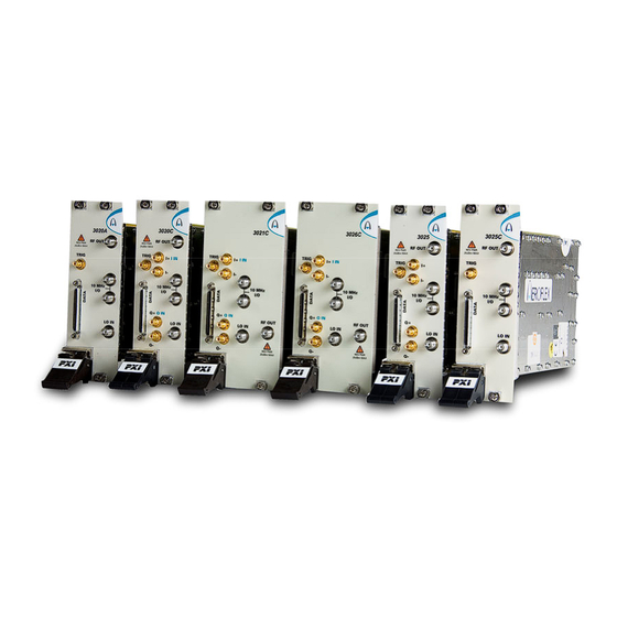
  • Page 9 This is the user manual for the 3020A, 3020C, 3021C, 3025, 3025C and 3026C Digital RF Signal Generators, which are referred to generically in this document as ‘3020 Series’. These Digital RF Signal Generators operate over the following frequency ranges: 3020A 250 MHz to 2.7 GHz...
  • Page 10 HF, VHF and UHF radio communications, especially important when testing multi-mode cellular terminals. Low noise and frequency-agile When used with a 3010 Series synthesizer, the 3020 Series provides the low noise and high switching speed necessary for high-productivity RFIC testing or the stimulus to frequency- hopping radios.
  • Page 11 GENERAL INFORMATION RF level accuracy and bursting The 3020 Series maintains accurate RF output levels to typically ±0.3 dB, and can generate modulated RF bursts to simulate TDMA signal characteristics. IQ digital modulation The 3020 Series provides high-quality digital modulation suitable for all common radio communications applications, either from the internal ARB or from an external source via the LVDS data connector.
  • Page 12 3020 Series module. Software A 3020 Series module is supplied with a VXI PNP driver and soft front panel for use as a standalone module. It is also supplied with an instrument-level signal generator soft front panel, a dll and a COM object, for use with a 3010 Series RF synthesizer.
  • Page 13 GENERAL INFORMATION Deliverable items • 3020 Series RF Signal Generator PXI module • PXI Modules CD-ROM (part no. 46886/028), containing soft front panels, drivers, application software, data sheets, installation guides, safety instructions, getting started and user manuals for this and other modules in the 3000 Series •...
  • Page 14 For the latest specifications, see the data sheet included on the CD-ROM (part no. 46886/028) or go to the Aeroflex website. All 3020 Series specifications are defined when used in conjunction with the 3010/11 RF Synthesizer PXI module and driver software supplied with the module.
  • Page 15 INSTALLATION Initial visual inspection Refer to the 3000 Series Common Installation Guide part no. 46892/663 on the PXI Modules CD-ROM, part no. 46886/028. Handling precautions Refer to the 3000 Series Common Installation Guide part no. 46892/663 on the PXI Modules CD-ROM, part no.
  • Page 16 INSTALLATION Airflow Fit slot blockers to all unused slots. Modules can overheat if the correct airflow is not maintained. Installing the module into the PXI chassis Refer to the 3000 Series Common Installation Guide part no. 46892/663 and Installation Guide for Chassis part no. 46882/697 on the PXI Modules CD-ROM, part no. 46886/028. These guides provide information such as specific precautions to take, positioning and fitting the modules, making connections for the LO and the 10 MHz reference signal, installing hardware drivers, and so on.
  • Page 17 INSTALLATION Overtightening will cause damage! Do not allow center pins to rotate! Do not allow the center pins of connectors to rotate when you connect and remove cables. Use a connector saver! Use a connector saver (part no. 46885/224): (a) on any SMA connector where the cable is routinely connected and disconnected (b) when the connector on the cable, or the cable end of the connector saver, has not been gauged.
  • Page 18 OPERATION Front-panel connectors SMA socket, 50 Ω. 1 RF OUT 2 I+ , I− , I IN Analog I output (I+ and I−), 50Ω single- ended, 100 Ω differential. SMB sockets. Option 01 only Analog I input (I IN), selectable 50Ω/100 kΩ.
  • Page 19 FRONT-PANEL CONNECTORS 1 I+ , I− , I IN Analog I output (I+ and I−), 50Ω single- ended, 100 Ω differential. SMB sockets. Option 01 only Analog I input (I IN), selectable 50Ω/100 kΩ. 2 10 MHz I/O Two SMA I/O sockets in parallel. REV PWR 25dBm MAX Input...
  • Page 20 CD-ROM). Access the soft front panel from the Windows Start menu under Programs\Aeroflex\PXI Module Front Panels\AF3020 Soft Front Panel. Or open the AF3020_sfp.exe file, which if you did not change the default location, is located with the VISA software.. The soft front panel, similar to that in Fig. 4, is displayed.
  • Page 21 SOFT FRONT PANEL Menu bar ARB handling RF settings Triggering Sample rate Boot C6352 Fig. 4 3025C soft front panel (other 3020 Series panels are similar) Artisan Technology Group - Quality Instrumentation ... Guaranteed | (888) 88-SOURCE | www.artisantg.com...
  • Page 22 Menu bar File Click File\Exit on the menu bar to close the application. Settings Settings\Load and Settings\Save on the menu bar allow you to load and save soft front panel configurations from and to your preferred locations. If you did not change the default location when installing the software, it is the same as for the VISA software (refer to the 3000 Series PXI Modules Common Installation Guide for details), and configurations are saved as .ini files.
  • Page 23 MENU BAR ON SOFT FRONT PANEL Settings\Routing Scenarios on the menu bar allows you to select a predefined routing matrix connection. A tick against the scenario’s title shows that it is selected. If you select a scenario, and then a second, any connected or enabled outputs common to both scenarios are overwritten by the second.
  • Page 24 List Strobe In List Strobe Out 3020 SERIES PXI MODULE C6286 DATA LVDS Marker 1–4 LVDS Aux[0]–[4] LVDS Spare 0–2 Fig. 6 Routing matrix in 3020 Series Artisan Technology Group - Quality Instrumentation ... Guaranteed | (888) 88-SOURCE | www.artisantg.com...
  • Page 25 Aeroflex if you need assistance in defining particular routing requirements. 3020 Series are hybrid slot-compatible PXI-1 peripheral modules, and so all but one of the parallel LBL outputs are grayed out and unavailable. Instead, the drop-down menu associated with LBL[6] provides a serial interface LA_SER.
  • Page 26 Output signals Input signals Fig. 7 Routing matrix inputs and outputs (other 3020 Series are similar) Routing matrix signals are shown in the following tables. All signals are TTL compatible and active high. Note that some signals apply to 3020C/3021C/3025C/3026C or 3020A/3025 only.
  • Page 27 MENU BAR ON SOFT FRONT PANEL Note: the labels shown below are prefixed af3020_ROUTE_ when using af3020_32.dll (see af3020_lib_const.h). If using afsiggen (preferred), the labels are prefixed afSigGenDll_rm (see afsiggen help file). Routing matrix data destinations: external signals Name in SFP Label Description PXI Trig[0]–[7]...
  • Page 28 MENU BAR ON SOFT FRONT PANEL Routing matrix data destinations: internal signals Name in SFP Label Description ARB Trigger ARB_TRIG Triggers the internal ARB when in triggered mode. RF Off Ext RFOFF_EXT Blanks the RF output when asserted. Mod Off Ext MODOFF_EXT Disables modulation when asserted.
  • Page 29 MENU BAR ON SOFT FRONT PANEL Routing matrix data sources: external signals Note that, in general, bidirectional external signals that have been enabled as outputs can still be used as a data source. Name in SFP Label Description PXI Trig[0]–[7] PXI_TRIG_N Signals from the PXI Trigger bus.
  • Page 30 MENU BAR ON SOFT FRONT PANEL Routing matrix data sources: internal signals Name in SFP Label Description ARB Marker 1–4 ARB_MARKER_N Four marker bits from the ARB. Each sample in the .AIQ file has four associated marker bits, which are generated synchronously with the samples.
  • Page 31 MENU BAR ON SOFT FRONT PANEL Example of using the routing matrix Configuring the front-panel SMB as a gating signal between PXI Trigger Bus 0 and the ARB trigger: • Connect Sync Gate Signal to PXI Trig[0] • Connect ARB Trigger to Sync Gate Out •...
  • Page 32 (Fig. 8). You may enable or disable additional instrument options if you have the appropriate password (available from the Aeroflex sales desk). Fig. 8 Options screen (example) Disabled options are shown grayed out. To enable an option, enter the appropriate password.
  • Page 33 The supplied plugin for use with a 3010 Series module is af3010_plugin.dll. Fig. 9 User calibration screen (other 3020 Series are similar) Artisan Technology Group - Quality Instrumentation ... Guaranteed | (888) 88-SOURCE | www.artisantg.com...
  • Page 34 MENU BAR ON SOFT FRONT PANEL IQ Calibration Differential IQ: there are two differential IQ calibrations: Cal Outputs is used to null out any DC offset on the differential outputs. Cal Inputs is used to null out DC offsets on the analog IQ input path. If you apply no signal, this cal nulls DC offsets internal to the module’s analog IQ input path.
  • Page 35 MENU BAR ON SOFT FRONT PANEL Help Help\Instrument Information on the menu bar provides the module’s PXI resource code and serial number, revision numbers for driver, FPGA and PCI, and its last calibration date. Help\About on the menu bar provides the version and date of the soft front panel. Artisan Technology Group - Quality Instrumentation ...
  • Page 36 Shows the frequency that needs to be set on the 3010 Series synthesizer to give the chosen RF frequency at the 3020 Series module’s output. Double-click in this field, copy the value, and paste into the RF Frequency (Hz) field on the 3010 Series module’s soft front panel.
  • Page 37 BOOT ON SOFT FRONT PANEL Reference Locked This indicator is lit when the 3020 Series module is locked to an external 10 MHz reference signal. If it is not lit, the external reference is missing. Artisan Technology Group - Quality Instrumentation ... Guaranteed | (888) 88-SOURCE | www.artisantg.com...
  • Page 38 RF settings The controls available in this group (here) allow you to configure up to 128 channels for frequency, level, leveling mode, and other parameters. These parameters are stored, and are recalled as each channel is selected. This selection can be manual (by clicking the up/down arrows of the RF Channel field) or by list mode operation.
  • Page 39 Click this to set up each of up to 64 channels (3020A/3025) or 128 channels (3020C/3021C/3025C/3026C). You can edit, copy and paste the settings to simplify setup. Fig. 10 Edit channel list settings (other 3020 Series are similar) Artisan Technology Group - Quality Instrumentation ... Guaranteed | (888) 88-SOURCE | www.artisantg.com...
  • Page 40 RF SETTINGS ON SOFT FRONT PANEL Edit the grid in the upper part of the screen by means of the fields in the lower part. Edit each channel individually or by range for: Channel RF Freq (Hz) RF Levelling Mode RF RMS (dBc) RF Level (dBm) RF Output Enable...
  • Page 41 Insert values and click Set for each field. You are asked to confirm each action. When finished, click Close to return to the Channel List screen. Fig. 11 Edit all channel settings (other 3020 Series are similar) Artisan Technology Group - Quality Instrumentation ... Guaranteed | (888) 88-SOURCE | www.artisantg.com...
  • Page 42 Note: the Required LO Freq (Hz) box shows the frequency that needs to be set on the 3010 Series synthesizer to give the chosen RF frequency at the 3020 Series module’s output. Step size: double-click on the step value under the frequency field to set up the size of frequency step.
  • Page 43 RF SETTINGS ON SOFT FRONT PANEL Gate RF If set to 1 (enabled), this turns the RF output for the active channel off when near to zero. This minimizes IQ leakage to a nominal –80 dBc during periods when the signal is ‘off’.
  • Page 44 RF SETTINGS ON SOFT FRONT PANEL Attenuator Hold As the step attenuator changes range, small changes in VSWR can occur. Check the box to freeze the attenuator on its current range. The maximum positive excursion is restricted to the 6 dB range of the attenuator pad (8 dB, 3020A only), but you can reduce the RF level over a range of up to 40 dB.
  • Page 45 RF SETTINGS ON SOFT FRONT PANEL Levelling Mode Leveling mode Internal ARB External Analogue IQ inputs (Opt. 01) Auto (RMS/Pk) Sets leveling automatically to RMS for ARB The set level is for files that contain appropriate header ® information ( files).
  • Page 46 RF SETTINGS ON SOFT FRONT PANEL Modulation Source Select between: LVDS (external modulation via DATA connector on front panel) ARB (internal modulation using the arbitrary waveform generator) None (CW) (no modulation, carrier wave only) Internal AM Internal FM External Analog (vector modulation) (allows use of IQ analog inputs when Option 001 is fitted) Actual Level Shows the current actual output level achieved by the module.
  • Page 47 Sample rate These controls are here. ARB Sample Rate (Hz) Set the ARB’s sample rate when Modulation Source is set to ARB. This is necessary only ® when the ARB file contains no header (files not generated using LVDS Sample Rate (Hz) Sets the LVDS sample rate when Modulation Source is set to LVDS.
  • Page 48 3020 Series digital RF signal generator. It is also possible to package and download files that have been created using other tools. Arbitrary ®...
  • Page 49 ARB HANDLING ON SOFT FRONT PANEL File Info Provides information about the currently selected ARB file, such as file name and maximum output level. Delete Deletes the currently selected ARB file from the specified catalog. Reload Reloads an ARB file from hard disk to the specified catalog. Reload All Reloads all ARB files from hard disk.
  • Page 50 Triggering These controls (here) provide trigger setup for the external ARB trigger. External ARB trigger sources are: PXI backplane (PXI trigger bus) LVDS AUXiliary inputs (front-panel DATA connector) TTL TRIG input on front panel (SMB) Star trigger (star controller card in Slot 2) Serial local bus (3020C/3021C/3025C/3026C only) LBL [1–13] (3020A/3025 only) Select trigger sources with the...
  • Page 51 TRIGGERING ON SOFT FRONT PANEL Trigger Mode Gated Begins playing the ARB file continuously on receipt of the leading edge of a gate pulse. After the trailing edge of the gate, the ARB file continues playing until its end, then stops. Single-shot Plays the ARB file once through.
  • Page 52 TRIGGERING ON SOFT FRONT PANEL Trigger Mode Start/Retrig The first trigger edge starts the ARB waveform, the next trigger edge restarts it immediately. Start/Stop The first trigger edge starts the ARB waveform, the next trigger edge stops it. Start Only The trigger edge starts the waveform.
  • Page 53 Text file af3020.doc 3020 Series function documentation af3020.hlp 3020 Series Visual BASIC function reference Windows Help file format af3020_C.hlp 3020 Series C language function reference We recommend that you use the C or Visual Basic formats, as these are easier to navigate.
  • Page 54 DRIVER EXPORT FUNCTIONS The file opens at the Contents page: Fig. 13 Online help contents — example Hyperlinks from here take you to Introduction Assumptions Error codes Functions listings. Artisan Technology Group - Quality Instrumentation ... Guaranteed | (888) 88-SOURCE | www.artisantg.com...
  • Page 55 DRIVER EXPORT FUNCTIONS Functions listings Functions are grouped by type. Click on the hyperlink for details of the function. Each function has a description of its purpose, and may have a list of parameters and return values. Fig. 14 Function description — example Artisan Technology Group - Quality Instrumentation ...
  • Page 56 Available options Option 01 Analog I & Q inputs and I & Q outputs Differential IQ When this option is fitted, Differential IQ displays the screen for setting up differential outputs (Fig. 15) and single-ended inputs. The module provides balanced baseband I and Q outputs suitable for feeding devices with differential inputs.
  • Page 57 OPTIONS Fig. 15 Differential IQ setup screen Output Enable enables or disables the differential IQ outputs. When set Off, the output is high impedance. When set On, the output impedance is 50 Ω. Modulation enables or disables the bias and offset voltages. When set Off, it zeroes bias, offset and signal voltages.
  • Page 58 OPTIONS IQ Gain (dB) specifies the relative amplitudes of the I and Q signals. Adding gain (+x dB) to the signal increases the magnitude of the I component by whilst decreasing the magnitude of the Q component by the same factor. Similarly, removing gain ( −...
  • Page 59 OPTIONS Single-ended pk-pk º Differential pk-pk I Offset (see note) Q Bias Gain Adding x dB increases I Level by x/2 and decreases Q Level by x/2. Removing x dB increases Q Level by x/2 and decreases I Level by x/2. C6169 This diagram represents a condition where the signal is output into a floating 100...
  • Page 60 OPTIONS Option 02 High speed frequency switching in DDS band Available on 3020C/3021C/3025C/3026C only. When this option is fitted, the settling time is that given in the data sheet. If Option 02 is not fitted, settling time is not faster than 1 ms. Option 03 1 Gbyte ARB memory Available on 3020C/3021C/3025C/3026C only.
  • Page 61 (document no. 46892/809), all supplied on the CD-ROM with the module, for detailed information on creating a fully functional digital signal generator instrument, using a 3020 Series Digital RF Signal Generator module and 3010/3011 RF Synthesizer together. The afSigGen soft front panel and afSigGen dll or afcomSigGen COM object combine the functions of the individual modules to provide a single interface with the appearance and functionality of an integrated instrument.
  • Page 62 Appendix A Format of ARB files General The ARB stores digital representations of waveforms. Any number of waveforms can be stored, up to a total capacity of 32 Msamples (3020A/3025) or 128 Msamples (3020C/3021C/3025C/3026C). For 3020C/3021C/3025C/3026C only, this can be extended to 256 or 512 Msamples by fitting Options 3 or 4 respectively.
  • Page 63 FORMAT OF ARB FILES An example showing data rates and sizes for an IS-95 waveform IS-95 has a chip rate of 1.2288 Mchip/s. For our purposes we will consider a chip to be the significant symbol. Each symbol must be sampled at least four times. This would give a rate of 4.9152 Msample/s.
  • Page 64 FORMAT OF ARB FILES Format for header of ARB IQ files (*.aiq) Comment No. of bytes [File] Date= Date file was created (mm/dd/yyyy) Time= Time file was created (hh:mm:ss) PackSWVers=nn.nn SW version of Packager (files that are created using software other than ®...
  • Page 65 FORMAT OF ARB FILES All headers are stored as ASCII strings, each line terminated with CR/LF. The header is terminated by a ^Z. Data following the header is the IQ and marker data stored as IQIQIQ… The format is: bit number bit number where Mn = marker number n, S = sign bit.
  • Page 66 Appendix B DATA connector and timing The DATA connector is a 68-way female VHDCI-type LVDS (low-voltage differential signaling) interface. It can be used to input data and associated control and timing signals. The DATA connector is shown in Fig. 17. LVDS data conforms to ANSI/TIA/EIA-644. C5504 Fig.
  • Page 67 DATA CONNECTOR AND TIMING Table 1 DATA pin-out Contact Function Contact Function AUX0- AUX0+ AUX1+ AUX1− AUX2+ AUX2− SPARE1+ SPARE1− SPARE2+ SPARE2− CLK_OUT+ CLK_OUT− CLK_IN+ CLK_IN− D0− D1− D2− D3− D4− D5− D6− D7− D8− D9− D10+ D10− D11+ D11− D12+ D12−...
  • Page 68 DATA CONNECTOR AND TIMING Contact Function Contact Function MARKER1+ MARKER1− MARKER2+ MARKER2− MARKER3+ MARKER3− MARKER4+ MARKER4− AUX3+ AUX3− AUX4+ AUX4− Artisan Technology Group - Quality Instrumentation ... Guaranteed | (888) 88-SOURCE | www.artisantg.com...
  • Page 69 DATA CONNECTOR AND TIMING LVDS data used as IQ input Data is supplied to the LVDS interface using a 16-bit bus. The D/A converters are 14 bits and by default the module uses bits [15:2]; however, it is possible to select to use [13:0] instead. Similarly, data is signed two’s complement by default, but it is possible to select unsigned instead.
  • Page 70 DATA CONNECTOR AND TIMING Output power level The IQ leveling loop is referenced to maximum I and Q level (1,1 on the vector diagram), and the maximum RF power using IQ data is also referenced to this. Output level for a modulated signal with constant envelope (for example, GSM) is reduced by 3 dB on the maximum available CW level.
  • Page 71 BRIEF TECHNICAL DESCRIPTION Introduction A 3020 Series module is a PXI digital RF signal generator. It contains IQ modulators, a leveling control system, step attenuators, and a dual-channel arbitrary waveform generator. It is used with an external source, preferably a 3010 Series RF synthesizer, which provides an LO signal.
  • Page 72 BRIEF TECHNICAL DESCRIPTION FREQUENCY IQ MOD DIVIDERS STEP 50 R RF OUTPUT MODULATOR 250 MHz to ATTENUATOR 2.7 GHz 250 MHz to 2.7 GHz DETECTOR LO IN 1.5 to 3 GHz IQ MOD MULTIPLEXER DIFF IQ OUT INPUT IQ SINGLE-ENDED CONDITIONING IQ IN OUTPUT IQ...
  • Page 73 BRIEF TECHNICAL DESCRIPTION FREQUENCY IQ MOD DIVIDERS STEP 50 R RF OUTPUT MODULATOR 100 MHz to ATTENUATOR 6 GHz 100 MHz to 6 GHz DETECTOR LO IN 1.5 to 3 GHz IQ MOD MULTIPLEXER DIFF IQ OUT INPUT IQ SINGLE-ENDED CONDITIONING IQ IN OUTPUT IQ...
  • Page 74 BRIEF TECHNICAL DESCRIPTION FREQUENCY 85 MHz to 3 GHz IQ MOD DIVIDERS 50 R MODULATOR STEP 85 MHz to RF OUTPUT ATTENUATOR 3 GHz 1 MHz to 3 GHz DETECTOR LO IN 1.5 to 3 GHz IQ MOD MULTIPLEXER 1 MHz to 85 MHz DIFF IQ OUT INPUT IQ SINGLE-ENDED...
  • Page 75 BRIEF TECHNICAL DESCRIPTION BYPASS 3 dB RF OUTPUT ATTENUATOR ≤ 3 GHz 100 kHz to 3 GHz +17 dBm, >85 MHz ≤ +14 dBm, DETECTOR AMPLIFIER FREQUENCY 85 MHz to 3 GHz IQ MOD DIVIDERS 50 R MODULATOR STEP 85 MHz to ATTENUATOR 3 GHz DETECTOR...
  • Page 76 BRIEF TECHNICAL DESCRIPTION FREQUENCY 85 MHz to 6 GHz IQ MOD DIVIDERS 50 R MODULATOR STEP 85 MHz to RF OUTPUT ATTENUATOR 6 GHz 1 MHz to 6 GHz DETECTOR LO IN 1.5 to 3 GHz IQ MOD MULTIPLEXER 1 MHz to 85 MHz DIFF IQ OUT INPUT IQ SINGLE-ENDED...
  • Page 77 BRIEF TECHNICAL DESCRIPTION BYPASS 3 dB RF OUTPUT ATTENUATOR ≤ 3 GHz 1 MHz to 6 GHz +17 dBm, >30 MHz ≤ +14 dBm, DETECTOR AMPLIFIER FREQUENCY 85 MHz to 6 GHz IQ MOD DIVIDERS 50 R MODULATOR STEP 85 MHz to ATTENUATOR 6 GHz DETECTOR...
  • Page 78 GLOSSARY ACLR Adjacent Channel Leakage Ratio: a measurement of transmitter performance for W-CDMA. It is the ratio of transmitted power to the power received (after filtering) in the adjacent RF channel. It describes the amount of distortion generated due to nonlinearities in RF components, and is a critical measurement for CDMA transmitters.
  • Page 79 GLOSSARY dynamic link library: an executable file that allows programs to share code and other resources necessary to perform particular tasks. Error Vector Magnitude is used to quantify the performance of a digital radio transmitter or receiver by measuring the deviation of received constellation points from their ideal positions. Frequency Modulation: modulation of the frequency of a carrier wave.
  • Page 80 GLOSSARY Plug-‘N’-Play PCI eXtensions for Instrumentation PXI Express Backwards-compatible with PXI, but providing faster timing and signal lines. Quadrature Amplitude Modulation: two amplitude-modulated carriers at the same frequency but at a relative phase angle of 90 degrees are combined in a single channel. This doubles the effective bandwidth of the transmission.
  • Page 81 GLOSSARY Unit Under Test Voltage-Controlled Oscillator: a frequency generator whose output frequency is a function of an applied voltage. If the applied voltage varies, the output is modulated. VHDCI Very High Density Cable Interconnect Very High Frequency: radio signals in the range 30 MHz to 300 MHz. VSWR Voltage Standing-Wave Ratio: the voltage ratio of the amplitude of a partial standing wave at an antinode (maximum) to the amplitude at an adjacent node (minimum), in a transmission...
  • Page 82 Artisan Technology Group is your source for quality new and certified-used/pre-owned equipment SERVICE CENTER REPAIRS WE BUY USED EQUIPMENT • FAST SHIPPING AND DELIVERY Experienced engineers and technicians on staff Sell your excess, underutilized, and idle used equipment at our full-service, in-house repair center We also offer credit for buy-backs and trade-ins •...

This manual is also suitable for:

3020a3020c3021c30253025c3026c