
Related Manuals for Aeroflex 3035C


Summary of Contents for Aeroflex 3035C
- Page 1 3035C Wideband RF Digitizer PXI Module Operating Manual Document no. 46892/836 Issue A provisional 28 February 2008...
-
Page 2: About This Manual
This manual applies to instruments with software driver issues of 3.0 and higher. This manual explains how to set up and configure an Aeroflex 3035C wideband RF digitizer PXI module. Where necessary, it refers you to the appropriate installation documents that are supplied with the module. -
Page 3: Intended Audience
PREFACE Intended audience Users who need to configure and operate the 3035C wideband RF digitizer to down-convert and digitize RF signals. This manual is intended for first-time users, to provide familiarity with basic operation. Programming is not covered in this document but is documented fully in the... -
Page 4: Associated Documentation
Install modules into a rack, interconnect 3000 Series PXI Modules Common Installation Guide them, power up and install drivers. Part no. 46882/663 On paper, on the CD-ROM and on www.aeroflex.com Set up a populated chassis ready for 3000 Series PXI Modules Installation Guide for use. -
Page 5: The Pxi Concept
VXI timing and triggering, and VXIplug&play instrument drivers to provide powerful and affordable systems. ® is a registered trademark of Aeroflex International Inc. in the US PXI™ is a registered trademark of the PXI Systems Alliance Windows™, Windows XP™ and Windows NT™ are trademarks of Microsoft Corporation... - Page 6 PREFACE Abbreviations/acronyms ACLR Adjacent Channel Leakage Ratio Adjacent Channel Power ACPR Adjacent Channel Power Ratio Analog-to-Digital Converter Amplitude Modulation Arbitrary Waveform Generator Continuous Wave Digital-to-Analog Converter Decibels Decibels relative to the carrier level Decibels relative to 1 mW Fast Fourier Transform Frequency Modulation FPGA Field Programmable Gate Array...
- Page 7 PREFACE PCI eXtensions for Instrumentation Radio Frequency Root Mean Square Soft Front Panel SubMiniature version A (connector) SubMiniature version B (connector) TDMA Time Division Multiple Access TRIG Trigger Transistor-Transistor Logic Unit Under Test Voltage-Controlled Oscillator VHDCI Very High Density Connector Interface VSWR Voltage Standing-Wave Ratio VMEbus Extension for Instrumentation...
-
Page 8: Chapter 1 General Information
Welcome to the operating manual for the 3035C Wideband RF Digitizer PXI module. The 3035C, when used with a 3010 Series PXI RF synthesizer module, forms a compact wideband RF digitizer that occupies four slots in a 3U PXI chassis. - Page 9 PCI and front-panel data interfaces. Software supplied with the module allows for spectrum analysis of the digitized signals. The 3035C can be used in RF test and measurement systems used in development or manufacturing. Applications span all areas of radio communications.
- Page 10 An instrument-level soft front panel is also provided, together with a dll and COM object, combining the controls of the 3035C together with the 3010 Series RF synthesizer. Refer to Getting Started with afDigitizer (part no. 46892/676) supplied on the PXI Modules CD-ROM part no.
-
Page 11: Deliverable Items
GENERAL INFORMATION Deliverable items • 3035C Wideband RF Digitizer PXI module • PXI Modules CD-ROM (part no. 46886/028), containing soft front panels, drivers, application software, data sheets, getting started and operating manuals for this and other modules in the 3000 Series •... -
Page 12: Chapter 2 Installation
Chapter 2 INSTALLATION WARNING Initial visual inspection Refer to the 3000 Series Common Installation Guide 46882/663. Handling precautions Refer to the 3000 Series Common Installation Guide 46882/663. Hardware installation Installing the module into the PXI chassis Refer to the 3000 Series Common Installation Guide 46882/663 and Installation Guide for Chassis 46882/667. -
Page 13: Connector Care And Maintenance
INSTALLATION Connector care and maintenance How to connect and torque an SMA connector 1 First, ensure that the mating halves of the connector are correctly aligned. 2 Next, engage the threads of the nut and tighten it by hand, ensuring that the mating halves do not move relative to each other. -
Page 14: Chapter 3 Operation
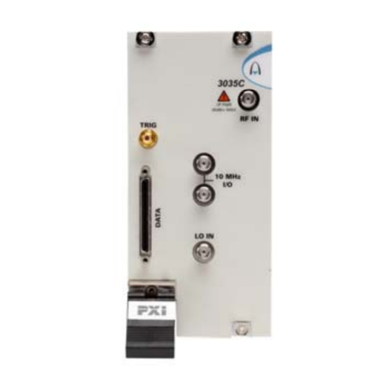
I/O, 14-bit IQ digital data output. Appendix A for details. LO IN TTL +ve or −ve edge. SMB socket, 50 Ω. TRIG Maximum safe power RF input: +30 dBm continuous (0 dB input attenuation) C6202 Fig. 3-1 3035C front panel... -
Page 15: Detailed Help Information
PXI Modules Common Installation Guide, part no. 46882/663). Access the soft front panel from the Windows Start menu under Programs\Aeroflex\PXI Module Front Panels\AF3030 Soft Front Panel. Or open the AF3030_sfp.exe file: this is in the C:\VXIPNP|WinNT\af3030\ directory on a Windows 2000 machine, for example. - Page 16 OPERATION IF/IQ data format Menu bar Boot C6216 Acquisition & Input conditioning RF tuning triggering Fig. 3-2 3035C soft front panel...
- Page 17 Soft front panel controls Menu bar File Save Captured Data (as ASCII file)… captures the 16-bit sample data into the specified ASCII file. Save Captured Data (as Binary file)… captures the 16-bit sample data into the specified binary file. Click Exit to close the application. Settings Load and Save allow you to load and save soft front panel configurations from and to your preferred locations.
- Page 18 MENU BAR ON SOFT FRONT PANEL LVDS allows you to set each LVDS Data, Auxiliary and Marker mode for input, output or tri-state (default) operation. Spare 0 is controlled by LVDS Data Mode. To use Spare 0 as a trigger input, set •...
- Page 19 Routing Matrix displays a matrix that provides interconnection between input and output signals on the PXI backplane bus, the DATA connector and the TRIG input, as shown diagrammatically in Fig. 3-3. This provides great flexibility in how you can route signals between modules. Fig. 3-3 Routing matrix in 3035C...
- Page 20 Aeroflex if you need assistance in defining particular routing requirements. 3035C is a hybrid slot-compatible PXI-1 peripheral module, and so all but one parallel LBL outputs are grayed out and unavailable. Instead, the drop-down menu associated with LBL[6]...
- Page 21 MENU BAR ON SOFT FRONT PANEL Output enable Input signal check boxes selection C6218 Output signals Input signals Fig. 3-4 Routing matrix inputs and outputs...
- Page 22 MENU BAR ON SOFT FRONT PANEL Optimization allows you to choose how the module compensates for the effect of temperature changes and RF frequency response. Auto Temperature Optimization (default) monitors the temperature of the module at regular intervals and adjusts the correction figure for the current temperature. You can turn this off if it might interfere with a time-critical measurement.
- Page 23 MENU BAR ON SOFT FRONT PANEL Options Allows you to enable or disable additional instrument options if you have the appropriate password (available from the Aeroflex sales desk). Click Edit… to display the options screen (Fig. 3-5). Fig. 3-5 Options screen Disabled options are shown grayed out.
- Page 24 MENU BAR ON SOFT FRONT PANEL View Allows you to view results in different formats. View FFT (default) displays a single graph showing logarithmic power versus frequency. The default span is 66% of full span. You can modify the top of screen reference power (dBm) and the vertical scaling (dB/div).
-
Page 25: Fft Display
MENU BAR ON SOFT FRONT PANEL FFT Display This menu is enabled only when View\View FFT is selected. It allows you to hide/display the graticule and save the dB levels of the trace as a .txt or other file. Graticule Visible hides or displays the graticule. The Span menu selects either Full or Truncated (approx. - Page 26 MENU BAR ON SOFT FRONT PANEL Time Series Display When View Time Series is selected, the Time Series Display menu is enabled, allowing you view I and Q traces on two separate graphs or overlaid in different colors. Graticule Visible hides or displays the graticule. IQ Separate Graphs displays separate graphs of Time Series (I) and Time Series (Q).
- Page 27 MENU BAR ON SOFT FRONT PANEL Capture By default, the module captures data to the screen (To Screen Only), but you can also capture results to ASCII or binary files whilst continuing to display on screen (To ASCII File and Screen; To Binary File and Screen). File Setup…...
- Page 28 Click Boot to initialize the module and view the Boot Resource window. Resources available for initializing are shown in blue. Select the 3035C you want to boot. Boot default FPGA configuration box. Check this. Do not change the configuration unless you are advised otherwise.
- Page 29 Shows the frequency to which a 3010 Series RF synthesizer module or other source should be set in order to provide the correct LO frequency for the 3035C. If you are using a 3010 Series module, simply double-click on the field, copy the value, and paste it into the RF Frequency (Hz) field on the 3010 Series module’s soft front panel.
-
Page 30: External Reference
RF TUNING ON SOFT FRONT PANEL External Reference Lock to 10MHz causes the ADC clock to lock to the 10 MHz reference connected to the 10 MHz I/O connector. Free Run allows internal oscillators to run at indeterminate frequencies. PCI Backplane causes the ADC clock to lock to the 10 MHz reference from the PCI backplane. -
Page 31: Input Conditioning
Input conditioning RF Input Level (dBm) Set this to the peak level of the input RF signal to insure the best dynamic range and signal-to- noise ratio. Set the RF input level using the up/down arrows or by entering the level, in the range −99.00 to +30.00 dBm in Auto Atten Config mode. - Page 32 INPUT CONDITIONING ON SOFT FRONT PANEL Atten Config Auto the RF input level set is used to optimize RF and IF attenuator gain settings automatically. Auto IF you have manual control of RF attenuation and preamp but the IF attenuator setting is automatically set by the driver. Manual you have complete control over the settings of the RF and IF attenuators and preamp;...
- Page 33 INPUT CONDITIONING ON SOFT FRONT PANEL Note: if no signal is present on the input, a sawtooth waveform is displayed on I and Q time series screens, due to a DC component introduced internally by the ADC transfer function. 3-20...
- Page 34 Acquisition & triggering Capture Trigger Allows you to select the trigger source from a drop-down list: Software trigger • SW_TRIG This is a non-triggered capture mode. Click on Start to capture samples (defined by Number of Samples) when in Single/Repeat mode, without waiting for any external event.
- Page 35 ACQUISITION AND TRIGGERING ON SOFT FRONT PANEL Hardware triggers Remaining triggers on the drop-down list are hardware triggers. When any of these is selected, triggering is dependent on trigger events, including the correct arming of the trigger. The module ignores triggers that occur during the sample capture. Refer to the help files for full details.
- Page 36 ACQUISITION AND TRIGGERING ON SOFT FRONT PANEL Trigger Type Set to Edge or Gate Edge/Gate Polarity Set +ve or –ve Trigger Offset Delay Delays the trigger by a specified number of output sample periods. Samples C5977 Trigger offset delay Trigger Max buffer length Pre-Trig Samples...
- Page 37 • Takes its trigger input from the slot to the left of the 3035C (viewed from the front panel), using the PXI local bus. This bit is common only to the 3035C and the module to its left. LVDS_M [1–4] •...
- Page 38 ACQUISITION AND TRIGGERING ON SOFT FRONT PANEL • INT_TIMER Takes its trigger from the internal timer. This timer trigger can also be routed to other modules using the routing matrix. Similarly, this timer can be synchronized with the external signal connected to the TIMER_SYNC signal in the routing matrix. Click Timer Settings…...
- Page 39 ACQUISITION AND TRIGGERING ON SOFT FRONT PANEL Fig. 3-6 Timer settings Use Channel when checked, lets you use a different timer period for each Timers channel. The timer period is determined by the active channel’s Period (see below), and applies while that channel is active. This mode is useful in setting up variable dwell list mode.
- Page 40 ACQUISITION AND TRIGGERING ON SOFT FRONT PANEL Period Sets the period of the active channel (in number of output samples) if Use Channel Timers is enabled. Otherwise, sets the common timer period in μs. Mark/space ratio in either mode is 50%.
- Page 41 ACQUISITION AND TRIGGERING ON SOFT FRONT PANEL • INT_TRIG Takes its trigger from the internal level trigger. 3-28...
- Page 42 ACQUISITION AND TRIGGERING ON SOFT FRONT PANEL Int Trigger Mode Select the internal level trigger mode: Absolute/Relative Absolute: the digitized signal is filtered using an absolute time constant. An internal level trigger is generated when the level of this filtered signal exceeds the absolute level trigger threshold (specified in dBm).
- Page 43 ACQUISITION AND TRIGGERING ON SOFT FRONT PANEL Signal envelope Envelope output, fast time constant filter Envelope output, slow time constant filter +ve trigger point Difference pulse Relative threshold level Internal trigger C6172 Fig. 3-7 Relative internal level trigger mode Trigger mode and control Mode: Selects Single-shot or Repeat data capture.
- Page 44 IF/IQ data format Sample Data Type Select IQ or IF sample data type. IQ Sample Data: output sample rate is determined by the Modulation Mode and • Decimation Ratio IF Sample Data: output sample rate is fixed at 250 MHz. •...
-
Page 45: Modulation Mode
IQ/IF DATA FORMAT ON SOFT FRONT PANEL Modulation Mode (IQ data format only) Sets the digital modulation mode. Select from Generic, UMTS, GSM, CDMA2000 1X or 2319 Emulation. The sample rate varies, depending upon modulation mode and decimation ratio: Generic: user-defined. Use this mode to create or emulate any modulation scheme. •... - Page 46 IQ/IF DATA FORMAT ON SOFT FRONT PANEL Pre-defined rates: UMTS data mode: 61.44 MHz/2 (where N = 1 to 10) • (4-N) GSM resampled IQ data mode: 13 MHz/(3 * 2 ), where N = 0 to 4 (2 times symbol •...
- Page 47 IQ/IF DATA FORMAT ON SOFT FRONT PANEL IQ Data Output Format Select 16- or 32-bit, subject to the modulation mode and decimation ratio chosen. Sample rates Modulation Decimation ratio IQ sample rate IQ data format (Msymbol/s) GENERIC variable 6 (when Output Sample Rate > 31.25 MHz) where n = 0 16/32 (when Output Sample Rate ≤...
-
Page 48: Fft Length
The name of the field changes to reflect the sample type selected. Sets the sample size (number of samples to be captured): 3035C: up to 64M IQ pairs with 32-bit storage, 128M IQ pairs with 16-bit storage, or 256 IF samples. - Page 49 List mode operation Introduction List mode operation associates a list address with a particular RF setup (channels 0–127). When the module is set to list mode operation, a new address, when strobed in, causes the module to change to the RF setup (channel) associated with that address. List mode operation facilitates fast channel hopping during, for example, testing of transmitter/receiver modules where numerous different RF level and frequency settings are needed.
- Page 50 LIST MODE Channel List Click Chan List on the soft front panel to display individual channel list settings (Fig. 3-8). This is where you define channel setup for list mode operation. Fig. 3-8 Edit channel list settings 3-37...
- Page 51 LIST MODE Edit individual channel parameters by selecting the specific channel. Channel parameters are: Freq (Hz) LO Position Atten Config RF Level (dBm) RF Atten (dB) IF Atten (dB) Period (μs/output samples Select the channel to be edited either by changing the channel number on the panel or by clicking on the corresponding channel row in the channel list.
- Page 52 LIST MODE Click Timer… to display the Timer Settings screen. Click Edit Range to display the Edit Channel Range screen (Fig. 3-9), which lets you apply changes to a set of channels simultaneously, speeding up channel setup. Define start and finish values for address numbers in the Chan range, from: and to: fields. Insert values and click Set for each field.
-
Page 53: List Mode Settings
LIST MODE Click List Mode to display the List Mode Settings screen, which lets you set up addressing and strobing, and the internal counter. List Mode Settings Click List Mode on the Channel List screen to display the List Mode Settings screen. From here, you can define the list address source, and how the strobe (internal or external) that actions a new list address is handled. -
Page 54: Strobe Polarity
LIST MODE Address Source Defines the source from which the seven-bit-wide list address is obtained. Manual: RF list addresses are register-driven values, manually controlled by setting the RF Channel. External: RF list addresses are sourced from the signal routing matrix (Fig. - Page 55 LIST MODE Counter Stop Defines the stop address of the list counter. If this value is greater than the value of Counter Start, the counter increments; otherwise it decrements. Setting this value also resets the list count to the next start address. Timer Dwell Defines the period of the list timer, in units of 0.1 μs.
-
Page 56: Driver Export Functions
Driver export functions On-line help and functional documentation for driver export functions are available on the CD-ROM supplied with your module. They are installed onto your computer at the same time as the drivers. Driver installation folder Find help and functional documentation in the driver installation folder on your computer. This is typically: C:\vxipnp\winnt\af3030 Help... - Page 57 DRIVER EXPORT FUNCTIONS The file opens at the Contents page: Fig. 3-11 Online help contents — example Hyperlinks from here take you to Introduction Assumptions Error codes Functions listings 3-44...
- Page 58 DRIVER EXPORT FUNCTIONS Functions listings Functions are grouped by type. Click on the hyperlink for details of the function. Each function has a description of its purpose, and may have a list of parameters and return values. Fig. 3-12 Function description — example 3-45...
- Page 59 PXI Studio User Guide (part no. 46892/809), both supplied on the CD-ROM with the module, for detailed information on creating a fully functional RF digitizer using the 3035C and 3010 Series modules together. The afDigitizer dlls and PXI Studio application combine the functions of the individual modules to provide a single interface with the appearance and functionality of an integrated instrument.
- Page 60 Appendix A DATA connector and timing The DATA connector is a 68-way female VHDCI-type LVDS (low-voltage differential signaling) interface. It can be used to output data and associated control and timing signals. The DATA connector is shown in Fig. A-1. LVDS data conforms to ANSI/TIA/EIA-644. C5504 Fig.
- Page 61 DATA CONNECTOR AND TIMING Table A-1 DATA pin-out Contact Function Contact Function AUX0- AUX0+ AUX1+ AUX1− AUX2+ AUX2− SPARE1+ SPARE1− SPARE2+ SPARE2− CLK_IN+ CLK_IN− CLK_OUT+ CLK_OUT− D0− D1− D2− D3− D4− D5− D6− D7− D8− D9− D10+ D10− D11+ D11− D12+ D12−...
-
Page 62: Data Format
DATA CONNECTOR AND TIMING Data format The data output to the DATA interface is real-time. In resample mode, data is output using a 250 MHz clock (but bursted to achieve the correct average sample rate). D0-D15 (Sample Sample Data Output Format: DATA) in Output 16-bit IQ: 2 x D[15:0], I followed by Q, D[0]=LSB. -
Page 63: Data Timing
DATA CONNECTOR AND TIMING Data timing Data transmission for generic modulation mode In this mode, IQ data is resampled to produce IQ data in the range 125 MHz/2 where N = 0 to 13. Example timing relationships between data rate and clock frequency for the DATA interface are shown in Fig. - Page 64 DATA CONNECTOR AND TIMING Data timing for UMTS modulation mode and decimation ratio of 2 The ADC in the module is clocked at a rate of 125 Ms/s. The module’s soft front panel allows both the modulation mode and the decimation ratio to be selected. IQSELECT_OUT is toggled only when an IQ data pair is being transmitted.
- Page 65 DATA CONNECTOR AND TIMING Data timing for UMTS modulation mode and decimation ratio of 4 The timing relationships for the DATA interface are as shown in Fig. A-5. The CLK_OUT signal is continuous and remains fixed at 125 MHz, irrespective of the modulation mode and the decimation rate.
- Page 66 DATA CONNECTOR AND TIMING Data timing for UMTS modulation mode and decimation ratio of 8 The timing relationships for the DATA interface are as shown in Fig. A-6. The CLK_OUT signal is continuous and remains fixed at 250 MHz, irrespective of the modulation mode and the decimation rate.
- Page 67 DATA CONNECTOR AND TIMING Data timing for CDMA2000 1X modulation mode If a modulation mode of CDMA2000 1X and a decimation value of 1 are both selected, IQ data is generated at eight times the CDMA2000 1X chip rate. As the chip rate is 1.2288 MHz, this gives an IQ sample rate of 9.8304 Ms/s.
- Page 68 DATA CONNECTOR AND TIMING Data transmission for GSM modulation mode and a decimation ratio of 1 In this mode the IQ data is resampled to produce IQ data at 16 times the GSM symbol rate of 270.83 kHz, that is, 4.333 Ms/s. The timing relationships for the DATA interface is as shown in Fig.
- Page 69 DATA CONNECTOR AND TIMING Data transmission for 2319E emulation mode In this mode, the IQ data is resampled to produce IQ data at 4.08 MHz with a decimation ratio of 16. The timing relationships for the DATA interface are as shown in Fig. A-10. Note that the CLK_OUT signal is continuous and that the frequency of the clock remains fixed at 125 MHz.
- Page 70 Licensor. By opening this Software package or commencing to use the software you accept the terms of this Agreement. If you do not agree to the terms of this Agreement please return the Software package unopened to Aeroflex International Limited or do not use the software.
- Page 71 5.3 If during the appropriate Warranty Period the Licensed Software does not conform substantially to the Software Product Descriptions, Data Sheets or Product Specifications Aeroflex will provide: 5.3.1 In the case of Embedded Software and at Aeroflex’s discretion either a fix for the problem or an effective and efficient work- around.
- Page 72 Licensed Software at the commencement of this Agreement. 8.3 Aeroflex shall not be liable to the Licensee for any loss of use or for loss of profits or of contracts arising directly or indirectly out of any such infringement of patent, registered design, trademark or copyright.
- Page 73 This Agreement shall be governed by the laws of England and shall be subject to the exclusive jurisdiction of the English courts. This agreement constitutes the whole Contract between the parties and may be changed only by memorandum signed by both parties. © AEROFLEX INTERNATIONAL LTD 2007...
- Page 74 As we are always seeking to improve our products, the information in this document gives only a general indication of the product capacity, performance and suitability,none of which shall form part of any contract. We reserve the right to make design changes without notice. www.aeroflex.com Email info-test@aeroflex.com November 2005...
Need help?
Do you have a question about the 3035C and is the answer not in the manual?
Questions and answers