Table of Contents
Advertisement
Quick Links
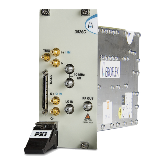
3000 Series PXI Modules
Common Installation Guide
© Aeroflex Ltd. 2010
Longacres House
Six Hills Way
Stevenage SG1 2AN
UK
No part of this document may be reproduced or transmitted in any form
or by any means, electronic or mechanical, including photocopying,
or recorded by any information storage or retrieval system,
without permission in writing by Aeroflex Ltd.
(hereafter referred to throughout the document as 'Aeroflex').
Document part no. 46892/663
Issue 13
29 November 2010
Advertisement
Table of Contents


Need help?
Do you have a question about the 3000 Series and is the answer not in the manual?
Questions and answers