
Related Manuals for Aeroflex 3020A


Summary of Contents for Aeroflex 3020A
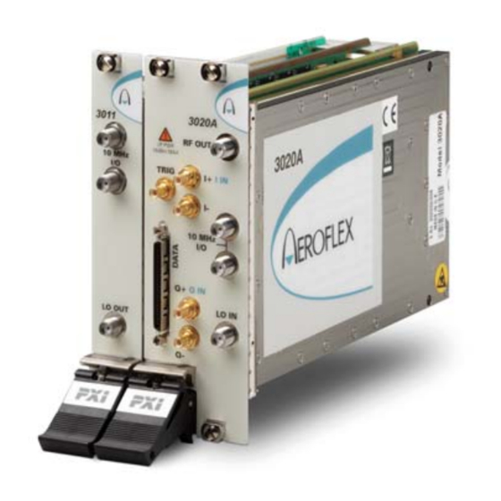
- Page 1 3020A Digital RF Signal Generator PXI Module Operating Manual Document no. 46892/717 Issue 4 14 March 2007...
-
Page 2: About This Manual
About this manual This manual applies to instruments with software issues of 2.0 and higher. This manual explains how to set up and configure an Aeroflex 3020A digital RF signal generator PXI module. Where necessary, it refers you to the appropriate installation documents that are supplied with the module. -
Page 3: Intended Audience
PREFACE Intended audience Users who need accurately-generated signals in the VHF and UHF spectrum. This manual is intended for first-time users, to provide familiarity with basic operation. Programming is not covered in this document but is documented fully in the help files that accompany the drivers and associated software on the CD-ROM. -
Page 4: Associated Documentation
PREFACE Associated documentation The following documentation covers specific aspects of this equipment: Part no. Compilation containing soft front panels, drivers, PXI Modules CD-ROM 46886/028 application software, data sheets, getting started and operating manuals for this and other modules in the 3000 Series. Part no. -
Page 5: The Pxi Concept
VXI timing and triggering, and VXIplug&play instrument drivers to provide powerful and affordable systems. ® is a registered trademark of Aeroflex International Inc. in the US PXI™ is a registered trademark of the PXI Systems Alliance Windows™, Windows XP™ and Windows NT™ are trademarks of Microsoft Corporation... - Page 6 PREFACE Abbreviations/acronyms ACP(R) Adjacent Channel Power (Ratio) Analog-to-Digital Converter Automatic Level Control Amplitude Modulation Arbitrary Waveform Generator Automatic Test Equipment Continuous Wave Digital-to-Analog Converter Decibels Decibels relative to the carrier level Decibels relative to 1 mW Error Vector Magnitude Frequency Modulation FPGA Field Programmable Gate Array Ground...
- Page 7 PREFACE Pk-Pk Peak-to-Peak PCI eXtensions for Instrumentation Radio Frequency Root Mean Square SDRAM Synchronous Dynamic RAM Soft Front Panel SubMiniature version A (connector) SubMiniature version B (connector) TDMA Time Division Multiple Access TRIG Trigger Transistor-Transistor Logic Unit Under Test Voltage-Controlled Oscillator VHDCI Very High Density Connector Interface VSWR...
-
Page 8: Chapter 1 General Information
Welcome to the operating manual for the 3020A Digital RF Signal Generator. The 3020A Digital RF Signal Generator operates over a frequency range of 250 MHz to 2.7 GHz and a level range of +5 dBm to −120 dBm. The RF output may be continuous wave (CW) or modulated. - Page 9 Low noise and frequency-agile When used with a 3010 Series synthesizer, the 3020A provides the low noise and high switching speed necessary for high-productivity RFIC testing or the stimulus to frequency- hopping radios.
- Page 10 GENERAL INFORMATION Analog I &Q inputs and outputs (optional) The 3020A can provide baseband I and Q output and CW RF output simultaneously. Differential analog I and Q outputs from the ARB are provided, with control of differential output level, DC bias and offset voltage.
- Page 11 3020A. Software The 3020A is supplied with a VXI PNP driver and soft front panel for use as a standalone module, and a signal generator soft front panel and dll or COM object for use with a 3010 or 3011 RF Synthesizer.
-
Page 12: Deliverable Items
GENERAL INFORMATION Deliverable items • 3020A RF Signal Generator PXI module • PXI Modules CD-ROM (part no. 46886/028), containing soft front panels, drivers, application software, data sheets and operating manuals for this and other modules in the 3000 Series •... -
Page 13: Chapter 2 Installation
Chapter 2 INSTALLATION WARNING Initial visual inspection Refer to the 3000 Series Common Installation Guide 46882/663. Handling precautions Refer to the 3000 Series Common Installation Guide 46882/663. Hardware installation Installing the module into the PXI chassis Refer to the 3000 Series Common Installation Guide 46882/663 and Installation Guide for Chassis 46882/667. -
Page 14: Torque Settings
INSTALLATION Coaxial connector torque settings and maintenance Torque settings Use a torque spanner to tighten SMA connectors together, in order to ensure consistent matching and to avoid mechanical stress. Torque settings for connectors are: 0.56 Nm test torque (development use, semi-permanent installations) 1 Nm final torque (permanent installations) Never use pliers to tighten connectors. -
Page 15: Chapter 3 Operation
68-way VHDCI connector for LVDS data I/O, 14-bit IQ digital data input. C5949 Appendix B for details. Fig. 3-1 3020A front panel TTL +ve or –ve edge. SMB socket, 50 Ω. TRIG Maximum safe power Reverse power handling: not to exceed +20 dBm... - Page 16 Open the AF3020_sfp.exe file: this is in the C:\VXIPNP|WinNT\af3020\ directory on a Windows NT machine, for example. It is also accessible from the Windows Start menu under Programs\Aeroflex\PXI Module Front Panels\AF3020 Front Panel. The soft front panel, similar to that in Fig. 3-2, is displayed.
- Page 17 OPERATION Menu bar ARB handling RF settings Triggering Sample rate Boot C6115 Fig. 3-2 3020A soft front panel...
- Page 18 Soft front panel controls Menu bar File Click Exit to close the application. Settings Load and Save allow you to load and save soft front panel configurations from and to your preferred locations. If you did not change the default location when installing the software, it is C:\VXIPNP\WinNT\af3020\settings, and configurations are saved as .ini files.
- Page 19 MENU BAR ON SOFT FRONT PANEL Routing Scenarios allows you to select a predefined routing matrix connection. A tick against the scenario’s title shows that it is selected. If you select a scenario, and then a second, any connected or enabled outputs common to both scenarios are overwritten by the second.
- Page 20 Routing Matrix displays a matrix that provides interconnection between input and output signals on the PXI backplane bus, the DATA connector and the 3020A’s internal circuitry, as shown diagrammatically in Fig. 3-3. This provides great flexibility in how you route signals between modules.
- Page 21 Load and Save commands in Settings, or use Routing Scenarios to access pre-set alternative routings, or contact Aeroflex if you need assistance in defining particular routing requirements.
- Page 22 MENU BAR ON SOFT FRONT PANEL Output enable Input signal check boxes selection C6118 Output signals Input signals Fig. 3-4 Routing matrix inputs and outputs...
- Page 23 (page 3-28). Options Allows you to enable or disable additional instrument options if you have the appropriate password (available from the Aeroflex sales desk). Click Edit to display the options screen (Fig. 3-5). Fig. 3-5 Options screen Disabled options are shown grayed out. To enable an option, enter the appropriate password.
- Page 24 MENU BAR ON SOFT FRONT PANEL User Cal Calibration is needed to ensure that some specifications — such as carrier leak — are met, and are guaranteed only if a user calibration has been performed. The module calibrates at the current frequency, or at a range of frequencies, and stores the results so that if you change frequency and return again, the calibration still applies.
- Page 25 MENU BAR ON SOFT FRONT PANEL IQ Calibration Differential IQ: there are two differential IQ calibrations: Cal Outputs is used to null out any DC offset on the differential outputs. Cal Inputs is used to null out DC offsets on the analog IQ input path. If you apply no signal, this cal nulls DC offsets internal to the module’s analog IQ input path.
- Page 26 Shows the frequency that needs to be set on the 3010 Series RF synthesizer to give the chosen RF frequency at the 3020A’s output. Double-click in this field, copy the value, and paste into the RF Frequency (Hz) field on the 3010 Series module’s soft front panel.
- Page 27 RF settings The controls available in this group allow you to configure up to 128 channels lists for frequency, level, leveling mode, and other parameters. These parameters are stored, and are recalled as each channel is selected. This selection can be manual (by clicking the up/down arrows of the RF Channel field) or by list mode operation.
- Page 28 RF SETTINGS ON SOFT FRONT PANEL Chan List Click this to set up each of up to 128 channels (Fig. 3-7). You can edit, copy and paste (page 3-4) the settings to make setup quick and easy. Fig. 3-7 Edit channel list settings 3-14...
- Page 29 RF SETTINGS ON SOFT FRONT PANEL Edit the grid in the upper part of the screen by means of the fields in the lower part. Most fields (Channel, RF Freq (Hz), etc) are similar to those on the soft front panel. Edit each channel individually or by range for: Channel RF Freq (Hz)
- Page 30 RF SETTINGS ON SOFT FRONT PANEL Click Edit Range to display the Edit Channel Range screen (Fig. 3-8), which lets you apply changes to a set of channels simultaneously, speeding up channel setup. Define start and finish values for address numbers in the Chan range, from: and to: fields. Insert values and click Set for each field.
- Page 31 Note: the Required LO Freq (Hz) box shows the frequency that needs to be set on the 3010/3011 synthesizer to give the chosen RF frequency at the 3020A’s output. Step size: double-click on the step value under the frequency field to set up the size of frequency step.
- Page 32 RF SETTINGS ON SOFT FRONT PANEL Gate RF If set to 1 (enabled), this turns the RF output for the active channel off when near to zero. This minimizes IQ leakage to a nominal –80 dBc during periods when the signal is ‘off’.
- Page 33 RF SETTINGS ON SOFT FRONT PANEL Levelling Mode Leveling mode Internal ARB External Analogue IQ inputs (Opt. 01) Auto Sets leveling automatically to RMS for The set level is for (RMS/Pk) ARB files that contain appropriate header ® information ( files).
-
Page 34: Modulation Source
RF SETTINGS ON SOFT FRONT PANEL Modulation Source Select between: LVDS (external modulation via DATA connector on front panel) ARB (internal modulation using the arbitrary waveform generator) None (CW) (no modulation, carrier wave only). None (CW) sets I and Q to maximum level. - Page 35 Sample rates ARB Sample Rate (Hz) Set the ARB’s sample rate when Modulation Source is set to ARB. This is necessary only ® when the ARB file contains no header (files not generated using LVDS Sample Rate (Hz) Sets the LVDS sample rate when Modulation Source is set to LVDS. The instrument calculates the interpolation automatically to place the interpolated frequency in the range 44 to 66 MHz.
- Page 36 (part no. 46882/627) that details the different modulation schemes supported. ® and its associated documentation are also available to download from the Aeroflex website http://www.aeroflex.com/iqcreator. ARB File Catalogue This field displays files currently loaded into the ARB’s memory.
- Page 37 ARB HANDLING ON SOFT FRONT PANEL Delete Deletes the currently selected ARB file from the specified catalog. Reload Reloads an ARB file from hard disk to the specified catalog. Reload All Reloads all ARB files from hard disk. This may improve performance if the ARB memory has become fragmented.
-
Page 38: Trigger Edge
Triggering Trigger setup for the external ARB trigger. ARB trigger sources are: PXI backplane Trigger bus LVDS AUXiliary inputs Front-panel DATA connector TTL TRIG input on front panel Star trigger Star controller card in Slot 2. Select trigger sources with the routing matrix (page 3-8). -
Page 39: Driver Export Functions
Help files are provided in three formats: af3020.doc 3020A function documentation Text file af3020.hlp 3020A Visual BASIC function reference Windows Help file format af3020_C.hlp 3020A C language function reference We recommend that you use the C or Visual Basic formats, as these are easier to navigate. - Page 40 DRIVER EXPORT FUNCTIONS The file opens at the Contents page: Fig. 3-9 Online help contents — example Hyperlinks from here take you to Introduction Assumptions Error codes Functions listings. 3-26...
- Page 41 DRIVER EXPORT FUNCTIONS Functions listings Functions are grouped by type. Click on the hyperlink for details of the function. Each function has a description of its purpose, and may have a list of parameters and return values. Fig. 3-10 Function description — example 3-27...
-
Page 42: Available Options
Available options Option 01 Analog I & Q inputs and I & Q outputs Differential IQ When this option is fitted, Differential IQ displays the screen for setting up differential outputs (Fig. 3-11) and single-ended inputs. The module provides balanced baseband I and Q outputs suitable for feeding devices with differential inputs. - Page 43 DRIVER EXPORT FUNCTIONS Output Enable enables or disables the differential IQ outputs. When set Off, the output is high impedance. When set On, the ouput impedance is 50 Ω. Modulation enables or disables the bias and offset voltages. When set Off, it zeroes bias, offset and signal voltages.
- Page 44 DRIVER EXPORT FUNCTIONS Single-ended pk-pk º Differential pk-pk I Offset (see note) Q Bias Gain Adding x dB increases I Level by x/2 and decreases Q Level by x/2. Removing x dB increases Q Level by x/2 and decreases I Level by x/2. C6169 This diagram represents a condition where the signal is output into a floating 100...
-
Page 45: Analog Modulation
DRIVER EXPORT FUNCTIONS Analog modulation Analog Modulation displays the screen for setting up internal AM and FM modulation (Fig. 3-13). Analog modulation is enabled when Modulation Source is set to Internal AM or Internal FM. The modulation source for internal AM/FM analog modulation is a sinusoid with user-settable frequency (modulation rate). - Page 46 3020A and 3010/3011 together. The afSigGen soft front panel and afSigGen dll or afSigGen COM object combine the functions of the individual modules to provide a single interface with the appearance and functionality of an integrated instrument.
-
Page 47: Appendix A Format Of Arb Files
Appendix A Format of ARB files General The ARB stores digital representations of waveforms. Any number of waveforms can be stored, up to a total capacity of 32 Msamples. The memory used is volatile. Each waveform consists of two components, I and Q. When the ARB is enabled and one of the waveforms selected, it is converted into a pair of analog signals that can be used to drive the I and Q channels of the RF modulator, or output as analog baseband IQ when Option 01 is fitted. - Page 48 FORMAT OF ARB FILES When the above waveform is selected and played, it is read out of the memory at 4.9152 Msample/s. The ARB interpolates this data stream so that it has a data rate of 58.9824 Msample/s. The data is written to the two 14-bit D-A converters at 58.9824 Msample/s. The analog outputs from the D-A converters are then filtered to remove switching and quantization noise and high-frequency images.
- Page 49 FORMAT OF ARB FILES Format for header of ARB IQ files (*.aiq) Comment No. of bytes [File] Date= Date file was created (mm/dd/yyyy) Time= Time file was created (hh:mm:ss) PackSWVers=nn.nn SW version of Packager (files that are created using software other than ®...
- Page 50 FORMAT OF ARB FILES All headers are stored as ASCII strings, each line terminated with CR/LF. The header is terminated by a ^Z. Data following the header is the IQ and marker data stored as IQIQIQ… The format is: bit number bit number where Mn = marker number n, S = sign bit.
- Page 51 Appendix B DATA connector and timing The DATA connector is a 68-way female VHDCI-type LVDS (low-voltage differential signaling) interface. It can be used to input data and associated control and timing signals. The DATA connector is shown in Fig. B-1. LVDS data conforms to ANSI/TIA/EIA-644. C5504 Fig.
- Page 52 DATA CONNECTOR AND TIMING Table B-1 DATA pin-out Contact Function Contact Function AUX0- AUX0+ AUX1+ AUX1− AUX2+ AUX2− SPARE1+ SPARE1− SPARE2+ SPARE2− CLK_OUT+ CLK_OUT− CLK_IN+ CLK_IN− D0− D1− D2− D3− D4− D5− D6− D7− D8− D9− D10+ D10− D11+ D11− D12+ D12−...
- Page 53 DATA CONNECTOR AND TIMING LVDS data used as IQ input Data is supplied to the LVDS interface using a 16-bit bus. The D/A converters are 14 bits and by default the module uses bits [15:2]; however, it is possible to select to use [13:0] instead. Similarly, data is signed two’s complement by default, but it is possible to select unsigned instead.
- Page 54 DATA CONNECTOR AND TIMING Markers There are four marker inputs/outputs on the DATA connector. The markers can be used for triggering and addressing.
-
Page 55: Chapter 4 Brief Technical Description
Chapter 4 BRIEF TECHNICAL DESCRIPTION Introduction The 3020A is a digital RF signal generator PXI module. It contains dividers to give a frequency range of 250 MHz to 2.7 GHz, IQ modulators, leveling control, step attenuation to −120 dBm, and a dual-channel arbitrary waveform generator. It does not contain a local oscillator (LO). - Page 56 The highest order of interpolation is 3072, which means the lowest sample rate is 14.323 kHz. These filters are used on both ARB and LVDS data. The 3020A applies all corrections to IQ data in the digital domain. This includes DC offset, gain imbalance and phase skew between I and Q.
- Page 57 BRIEF TECHNICAL DESCRIPTION The leveling loop derives its error signal by comparing the input to the comparator from the RF detector ADC, and the wanted IQ power. The IQ power is converted to detector volts in a look-up table. During bursted IQ data, the loop can be frozen while ramping IQ data up or down, and can also switch off the signal between bursts, improving on-off ratio.
- Page 58 BRIEF TECHNICAL DESCRIPTION The detector output is amplified and buffered before being fed back to the logic board for A-D conversion. A temperature-sensing mode is provided, where the detector is disabled and the output replicates the voltage. This can be measured and used to periodically adjust calibration in accordance with temperature and stored data.
- Page 59 BRIEF TECHNICAL DESCRIPTION In differential output mode, I and Q outputs from the logic and control board are buffered and pass through variable attenuators that provide up to 22.5 dB attenuation in 1.5 dB steps. They are then amplified by switched gain power stages, formed of paralleled amplifiers in order to provide low noise.
- Page 60 BRIEF TECHNICAL DESCRIPTION BAND FREQUENCY DIVIDER ¸ BAND BAND 2 to 130 dB FREQUENCY IQ MOD STEP DIVIDER ATTENUATOR 50 R RF OUTPUT ATTEN ¸ 250 MHz to 2.7 GHz 8 dB 250 MHz to 2.7 GHz FREQUENCY DIVIDER ¸ SHAPER DETECTOR LO IN...
-
Page 61: Chapter 5 Acceptance Testing
LO frequency for the signal generator. If a 3011 PXI RF Synthesizer is being used as an LO for the 3020A, then control of the 3011 and 3020A is greatly simplified by using the SigGen SFP. This controls both modules together so that the LO is automatically set to the required frequency. - Page 62 ACCEPTANCE TESTING Both SFPs are on the supplied CD−ROM (part no. 46886/028) as part of the common installation. Follow the instructions provided in the 3000 Series Common Installation Guide (part no. 46882/663) to ensure that this software is correctly installed. Each test procedure relies on the module being set to its power−up conditions.
-
Page 63: Recommended Test Equipment
Description Minimum specification Example Test parameters PXI synthesizer or 1.5 GHz to 3 GHz, 0 dBm Aeroflex 3011, or Aeroflex signal generator 3413 or 2032 Power meter and sensor 1.5 GHz to 2.7 GHz Aeroflex 6960B and 6912 RF level accuracy Spectrum analyzer 250 MHz to 8.1 GHz... -
Page 64: Test Precautions
ACCEPTANCE TESTING Test precautions To ensure minimum errors and uncertainties when making measurements, it is important to observe the following precautions: Always use recently calibrated test equipment, with any correction figures taken into • account, so as to establish a known traceable limit of performance uncertainty. This uncertainty must be allowed for in determining the accuracy of measurements. - Page 65 Checking that the UUT powers up correctly This test ensures that the 3020A powers up in a satisfactory manner and that the internal self- tests do not report any errors. This test assumes that instrument is fitted in a PXI chassis and that the supplied installation software is installed on the host controller.
- Page 66 This test checks correct operation of the frequency dividers used to generate frequencies down to 250 MHz. As the local oscillator is locked to the frequency counter, the test limits are ±1 count. 3011 synthesizer 3020A 3011 RF OUT RF OUT REV PWR...
- Page 67 ACCEPTANCE TESTING Connect the test equipment as shown in Fig. 5-1. On the UUT set: RF Frequency (Hz) 250000000 (250 MHz) (may be entered as 25e7) RF Level (dBm) Record the frequency measured by the counter against each of the UUT’s RF frequencies shown in Table 5-1.
- Page 68 The attenuator test measures the performance of the output attenuator at defined points • across the frequency band. ALC flatness 3011 synthesizer 3020A 3011 RF OUT REV PWR RF OUT Power meter 20dBm MAX...
- Page 69 ACCEPTANCE TESTING Connect the test equipment as shown in Fig. 5-2. On the UUT set: RF Frequency (Hz) 250100000 (250.1 MHz) (may be entered as 250.1e6) RF Level (dBm) Set the signal generator LO and the UUT to the frequencies and levels shown in Table 5-2, recording the output level measured by the power meter.
- Page 70 ACCEPTANCE TESTING Table 5-2 ALC flatness results Test LO frequency RF level Minimum Result (dBm) Maximum frequency (MHz) (dBm) (dBm) (MHz) 250.1 2000.8 +5 dBm +4.4 +5.6 +0 dBm −0.6 +0.6 −2.99 dBm −3.59 −2.39 −3 dBm −3.4 −2.6 −10.99 dBm −11.59 −10.39 3000...
- Page 71 ACCEPTANCE TESTING Test LO frequency RF level Minimum Result (dBm) Maximum frequency (MHz) (dBm) (dBm) (MHz) +0 dBm +0.6 −0.6 −2.99 dBm −3.59 −2.39 −3 dBm −3.4 −2.6 −10.99 dBm −11.59 −10.39 1000.1 2002.2 +5 dBm +4.4 +5.6 +0 dBm −0.6 +0.6 −2.99 dBm...
- Page 72 ACCEPTANCE TESTING Test LO frequency RF level Minimum Result (dBm) Maximum frequency (MHz) (dBm) (dBm) (MHz) −10.99 dBm −11.59 −10.39 1625 1625 +5 dBm +4.4 +5.6 +0 dBm −0.6 +0.6 −2.99 dBm −3.59 −2.39 −3 dBm −3.4 −2.6 −10.99 dBm −11.59 −10.39 1750...
- Page 73 ACCEPTANCE TESTING Test LO frequency RF level Minimum Result (dBm) Maximum frequency (MHz) (dBm) (dBm) (MHz) −2.99 dBm −3.59 −2.39 −3 dBm −3.4 −2.6 −10.99 dBm −11.59 −10.39 2375 2375 +5 dBm +4.4 +5.6 +0 dBm −0.6 +0.6 −2.99 dBm −3.59 −2.39 −3 dBm...
- Page 74 0 dBm is measured again and is correlated with that measured on the power meter. The lower levels are then measured on the spectrum analyzer relative to the measurement taken at 0 dBm. 3011 synthesizer 3020A 3011 RF OUT RF OUT REV PWR...
- Page 75 ACCEPTANCE TESTING On the UUT set: RF Frequency (Hz) 250100000 (250.1 MHz) (may be entered as 250.1e6) RF Level (dBm) With the spectrum analyzer set to the same frequency as the UUT, use the marker facility to measure the amplitude of the displayed signal. Using suitable span, filter and attenuation settings, record the level measured on the spectrum analyzer at each of the levels shown in Table 5-3.
- Page 76 ACCEPTANCE TESTING Table 5-3 Attenuator results at 250.1 MHz Test RF level Level Level Minimum Result Maximum frequency frequency (dBm) measured measured (dBm) (dBm) (dBm) (MHz) (MHz) on power meter spectrum (dBm) analyzer (dBm) 250.1 2000.8 −0.6 +0.6 −3 −3.6 −2.4 −8 −8.6...
- Page 77 ACCEPTANCE TESTING Table 5-4 Attenuator results at 500.1 MHz Test RF level Level Level Minimum Result Maximum frequency frequency (dBm) measured measured (dBm) (dBm) (dBm) (MHz) (MHz) on power meter spectrum (dBm) analyzer (dBm) 500.1 2000.4 −0.6 +0.6 −3 −3.6 −2.4 −8 −8.6...
- Page 78 ACCEPTANCE TESTING Table 5-5 Attenuator results at 1000.1 MHz Test RF level Level Level Minimum Result Maximum frequency frequency (dBm) measured measured (dBm) (dBm) (dBm) (MHz) (MHz) on power meter spectrum (dBm) analyzer (dBm) 1000.1 2000.2 −0.6 +0.6 −3 −3.6 −2.4 −8 −8.6...
- Page 79 ACCEPTANCE TESTING Table 5-6 Attenuator results at 1500.1 MHz Test RF level Level Level Minimum Result Maximum frequency frequency (dBm) measured measured (dBm) (dBm) (dBm) (MHz) (MHz) on power meter spectrum (dBm) analyzer (dBm) 1500.1 1500.1 −0.6 +0.6 −3 −3.6 −2.4 −8 −8.6...
- Page 80 ACCEPTANCE TESTING Table 5-7 Attenuator results at 2000.1 MHz Test RF level Level Level Minimum Result Maximum frequency frequency (dBm) measured measured (dBm) (dBm) (dBm) (MHz) (MHz) on power meter spectrum (dBm) analyzer (dBm) 2000.1 2000.1 −0.6 +0.6 −3 −3.6 −2.4 −8 −8.6...
- Page 81 ACCEPTANCE TESTING Table 5-8 Attenuator results at 2699.9 MHz Test RF level Level Level Minimum Result Maximum frequency frequency (dBm) measured measured (dBm) (dBm) (dBm) (MHz) (MHz) on power meter spectrum (dBm) analyzer (dBm) 2699.9 2699.9 −0.6 +0.6 −3 −3.6 −2.4 −8 −8.6...
-
Page 82: Carrier Harmonics
ACCEPTANCE TESTING Spectral purity tests Carrier harmonics 3011 synthesizer 3020A 3011 RF OUT REV PWR RF OUT 20dBm MAX 10 MHz TRIG I IN 10 MHz I/O 10 MHz 10 MHz I/O Spectrum analyzer Q IN LO IN LO OUT... - Page 83 ACCEPTANCE TESTING With the spectrum analyzer set to the same frequency as the UUT, use the marker facility to measure the amplitude of the displayed signal. Using Table 5-9, set the spectrum analyzer to f * 2 and f * 3, and measure the 2 and 3 harmonics relative to the reading obtained in (3).
- Page 84 ACCEPTANCE TESTING Carrier sub-harmonics Sub-harmonic signals are generated as part of the carrier frequency generation process and are measured relative to the carrier. Connect the test equipment as shown in Fig. 5-4. On the UUT set: RF Frequency (Hz) 375000001 (375.000001 MHz) −2.99 RF Level (dBm) With the spectrum analyzer set to the same frequency as the UUT, use the marker...
- Page 85 ACCEPTANCE TESTING Table 5-10 Carrier sub−harmonic results at −2.99 dBm Test Harmonic Sub- Result Limit frequency frequency ratio harmonic (dBc) (dBc) (MHz) (MHz) frequency (MHz) 375.00000 1500.0000 187.50000 −30 382.5 1530 191.25 −30 2320 −30 1160 2320 −30 1160 2320 −30 1500.1 1500.1...
- Page 86 Modulation tests Linearity (ACPR) and EVM ® This test may only be performed on a 3020A fitted with Options 100 and 102 ( 3G CDMA License). A CDMA single-carrier, 64-channel, test model 1 waveform is used to modulate the carrier, and the spectrum analyzer is used to measure the ACPR.
- Page 87 ACCEPTANCE TESTING Connect the test equipment as shown in Fig. 5-4. On the UUT set: RF Frequency (Hz) 2100000000 (2.1 GHz) (may be entered as 21e8) RF Level (dBm) Modulation Source Under View Controls, click on Arb — the ARB File Catalogue window opens. Click on Add and browse and locate ats_3gpp_fdd_fwd_tm1_64ch_sc0_v5pt1.aiq Click on Open.
-
Page 88: Third Order Intermodulation Distortion
ACCEPTANCE TESTING Third order intermodulation distortion The required test tone waveforms, which produce a double-sideband suppressed carrier suitable for testing intermodulation distortion (IMD), are included in SigGen SFP. Connect the test equipment as shown in Fig. 5-4. On the UUT set: RF Frequency (Hz) 250000000 (250 MHz) (may be entered as 25e7) - Page 89 ACCEPTANCE TESTING Table 5-13 Intermodulation distortion results Carrier LO frequency Lower IMD Upper IMD Limit (dBc) frequency (MHz) (MHz) product product 2000 −50 2000 −50 3000 −50 1000 2000 −50 1250 2500 −50 1500 3000 −50 1750 1750 −50 2000 2000 −50 2250...
- Page 90 Licensor. By opening this Software package or commencing to use the software you accept the terms of this Agreement. If you do not agree to the terms of this Agreement please return the Software package unopened to Aeroflex International Limited or do not use the software.
- Page 91 5.3 If during the appropriate Warranty Period the Licensed Software does not conform substantially to the Software Product Descriptions, Data Sheets or Product Specifications Aeroflex will provide: 5.3.1 In the case of Embedded Software and at Aeroflex’s discretion either a fix for the problem or an effective and efficient work- around.
- Page 92 Licensed Software at the commencement of this Agreement. 8.3 Aeroflex shall not be liable to the Licensee for any loss of use or for loss of profits or of contracts arising directly or indirectly out of any such infringement of patent, registered design, trademark or copyright.
- Page 93 This Agreement shall be governed by the laws of England and shall be subject to the exclusive jurisdiction of the English courts. This agreement constitutes the whole Contract between the parties and may be changed only by memorandum signed by both parties. AEROFLEX INTERNATIONAL LTD 2004...
- Page 94 As we are always seeking to improve our products, the information in this document gives only a general indication of the product capacity, performance and suitability,none of which shall form part of any contract. We reserve the right to make design changes without notice. www.aeroflex.com Email info-test@aeroflex.com November 2005...
Need help?
Do you have a question about the 3020A and is the answer not in the manual?
Questions and answers