
Related Manuals for Aeroflex 3060 Series


Summary of Contents for Aeroflex 3060 Series
- Page 1 sales@artisantg.com artisantg.com (217) 352-9330 | Visit our website - Click HERE...
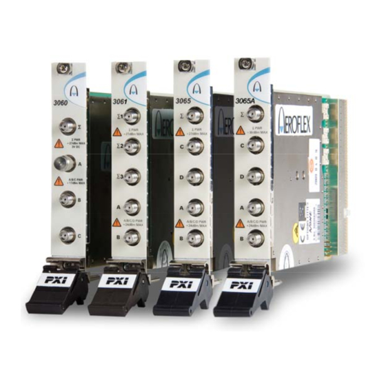
- Page 2 3060, 3061, 3065, 3065A (3060 Series) RF Combiner PXI Modules User Manual Document no. 46892/762 Issue 8 26 July 2011...
-
Page 3: About This Manual
PREFACE About this manual This manual explains how to set up and configure an Aeroflex 3060, 3061 or 3065 RF combiner PXI module. Where necessary, it refers you to the appropriate installation documents that are supplied with the module. Please note: this manual applies only when the instrument is used with the supplied software. -
Page 4: Intended Audience
Driver version This PXI RF module is designed to be used with the latest software driver version supplied on the Aeroflex 3000 Series PXI Modules CD-ROM, part no. 46886/028. Operation with earlier versions of driver software may not be supported. -
Page 5: Associated Documentation
3000 Series PXI Modules Common Installation Guide them, power up and install drivers Part no. 46892/663 On the CD-ROM and at www.aeroflex.com/ Set up a populated chassis ready for use 3000 Series PXI Modules Installation Guide for Chassis Part no. 46892/667 On the CD-ROM and at www.aeroflex.com/... -
Page 6: The Pxi Concept
(see Fig. 1), which allows them to be inserted into both hybrid slots and standard PXI-1 slots. Because of the reduced connectivity of Aeroflex hybrid-compatible PXI modules, the PXI parallel local bus LBL[0]–[12] disappears, to be replaced by the serial connection LBL[6],... - Page 7 PREFACE Fig. 1 Standard PXI 1-slot connector (L) and hybrid-compatible PXI connector (R) This table shows which Aeroflex PXI combiner modules fit only in a standard 1-slot, and which fit in both hybrid-compatible and standard slots: 3060 Standard PXI 1-slot...
-
Page 8: General Information
GENERAL INFORMATION Introduction This is the user manual for the 3060, 3061 and 3065 RF combiner PXI modules, which are referred to generically in this document as ‘3060 Series’. These combiner PXI modules operate over the following frequency ranges: 3060 250 MHz to 2.7 GHz... - Page 9 GENERAL INFORMATION 3060 Series combiners store their own path loss calibration data, which can be accessed via software calls to the driver. Combiners provide a single output from any combination of input ports. Each port is bi- • directional, allowing many system configurations. Port D (3065/3065A only) allows for a second output or input channel, or for testing of multifunction mobile telephones that support non-cellular functions.
- Page 10 GENERAL INFORMATION 3061 Combined output A, B to SUM 1, 2 or 3 Switched connection A to B...
- Page 11 GENERAL INFORMATION 3065 Combined output A, B, C to SUM Switched connection A to B and C to D A to D and C to B Switched and combined A to B and C to SUM C to B and A to SUM C to D and A, B to SUM A to D and C, B to SUM...
- Page 12 C6399 Applications 3060 Series combiners can be used in radio test applications such as transceiver testing, where the combined port Σ acts as a single-port duplex connection, one or two RF sources provide TX stimulus inputs, and an RF signal analysis instrument connected to the third port measures the DUT’s TX parameters.
- Page 13 GENERAL INFORMATION Software A 3060 Series combiner is supplied with a VXI PNP driver and soft front panel, and a COM object and a C interface DLL that provide similar functionality to the driver. PXI Studio, also supplied with the module, configures your PXI modules as logical instruments using an intuitive and powerful graphical interface .
-
Page 14: Deliverable Items
GENERAL INFORMATION Deliverable items 3060 Series RF Signal Generator PXI module • PXI Modules CD-ROM (part no. 46886/028), containing soft front panels, drivers, • application software, data sheets, installation guides, safety instructions, getting started and user manuals for this and other modules in the 3000 Series 3000 Series PXI Modules Safety Instructions: printed item, part no. -
Page 15: Specifications
For the latest specifications, see the data sheet included on the CD-ROM (part no. 46886/028) or go to the Aeroflex website. All 3060 Series specifications are defined when used in conjunction with the driver software supplied with the module. Warm-up time Allow at least twenty minutes for a module to warm up and meet its specifications fully after booting. -
Page 16: Installation
INSTALLATION WARNING Initial visual inspection Refer to the 3000 Series Common Installation Guide part no. 46892/663 on the PXI Modules CD-ROM, part no. 46886/028. Handling precautions Refer to the 3000 Series Common Installation Guide part no. 46892/663 on the PXI Modules CD-ROM, part no. -
Page 17: Hardware Installation
INSTALLATION Hardware installation WARNING Before installing the module into the chassis, check inside the chassis: (a) that no foreign conductive bodies are present between pins on the backplane connectors (b) that no pins on the backplane connectors are bent or damaged. Installing the module into the PXI chassis Refer to the 3000 Series Common Installation Guide part no. -
Page 18: Connector Care And Maintenance
INSTALLATION Connector care and maintenance How to connect and torque an SMA connector First, ensure that the mating halves of the connector are correctly aligned. Next, engage the threads of the nut and tighten it by hand, ensuring that the mating halves do not move relative to each other. -
Page 19: Maintenance
INSTALLATION Use a connector saver! Use a connector saver (part no. 46885/224, supplied): (a) on any connector where the cable is routinely connected and disconnected (b) when the connector on the cable, or the cable end of the connector saver, has not been gauged. -
Page 20: Operation
OPERATION Front-panel connectors Σ Combined output. SMA socket, 50 Ω. Individual inputs. SMA socket, 50 Ω. A, B, C 3060 S PWR S PWR Maximum safe powers 27dBm MAX 27dBm MAX Σ port: +27 dBm, 3 V dc continuous A, B, C ports: +24 dBm A/B/C PWR A/B/C PWR 17dBm MAX... - Page 21 OPERATION S1, S2, S3 Switched combined outputs. SMA socket, 50 Ω. Individual inputs. SMA socket, 50 Ω. 3061 A, B S1, S2, S3 PWR S1, S2, S3 PWR +30dBm MAX Maximum safe powers S1, S2, S3 ports: +30 dBm, 40 V dc continuous +33 dBm mark:space 1:1 where mark <0.5 ms...
- Page 22 OPERATION Σ Combined output. SMA socket, 50 Ω. A, B, C, D Individual inputs/outputs. SMA socket, 50 Ω. 3065 S PWR S PWR +27dBm MAX Maximum safe powers Σ port: +27 dBm, 3 V dc continuous +30 dBm mark:space 1:8 where mark <0.5 ms A, B, C, D ports: +24 dBm A/B/C/D PWR...
- Page 23 OPERATION Σ Combined output. SMA socket, 50 Ω. A, B, C, D Individual inputs/outputs. SMA socket, 50 Ω. 3065A S PWR S PWR +30dBm MAX Maximum safe powers Σ port: +30 dBm, 3 V dc continuous +33 dBm mark:space 1:8 where mark <0.5 ms A, B, C, D ports: +24 dBm A/B/C/D PWR...
-
Page 24: Detailed Help Information
CD-ROM). Access the soft front panel from the Windows Start menu under Programs\Aeroflex\PXI Module Front Panels\AF3060 Soft Front Panel. Or open the af3060_sfp.exe file, which if you did not change the default location, is located with the VISA software. The soft front panel, similar to that in Fig. 6, is displayed. - Page 25 OPERATION Menu bar Routing Path loss Boot C6358 Fig. 6 3061 combiner soft front panel (other 3060 Series panels are similar) Menu bar File Click Exit on the menu bar to close the application.
- Page 26 OPERATION Settings Load and Save on the menu bar allow you to load and save soft front panel configurations from and to your preferred locations. If you did not change the default location when installing the software, it is the same as for the VISA software (refer to the 3000 Series PXI Modules Common Installation Guide for details), and settings are saved as .ini files.
- Page 27 Boot Resource window. Resources available for initializing are shown in blue. Select the 3060 Series module you want to boot. Click OK. While you select the boot resource, the indicator is amber. Once the module has initialized, the indicator changes to green within a few seconds.
- Page 28 OPERATION Path Information This displays the loss, in dB, of the selected combiner path at the frequency entered in the RF Frequency (Hz) field. For example, A => B (dB) displays the dB loss between the A and B ports at the specified frequency. Loss values are temperature-compensated to maintain the accuracy of the factory calibrations.
- Page 29 OPERATION HW channel control Tick this box to cause the 3061 to take its channel number from the list address via the routing matrix, allowing the hardware to control both list addresses and combiner switching. Route LA_SER to whichever source is providing the list addresses. The 3061 supports serial addressing only.
-
Page 30: Basic Configuration
OPERATION Switching schemes Here are some examples of how you can use a 3060 Series module and other PXI components to provide efficient and economical test setups. We have written an application note (number 46891/985) that contains much useful information about using 3060 Series modules in different applications common to RF device testing: download it from the Aeroflex website. - Page 31 OPERATION 3020 Series RF signal generator SUM 1 UUT 1 SUM 2 UUT 2 SUM 3 UUT 3 3030 Series digitizer RF BLOCK CONTROL 3061 C6361 Fig. 9 Transceiver test (3061)
- Page 32 OPERATION 3020 Series RF signal generator 50 W 3020 Series RF signal generator 3030 Series digitizer RF BLOCK CONTROL 3065 C6360 Fig. 10 Transceiver test (3065) These two configurations connect one or two signal sources and a digital analyzer to the unit(s) under test (UUT) for amplifier or mixer intermodulation testing.
- Page 33 OPERATION Testing with additional non-cellular function 3020 Series RF signal generator 3020 Series non-cellular RF signal generator cellular 3030 Series digitizer RF BLOCK CONTROL 3065 C6362 Fig. 11 Cellular and non-cellular transceiver test This configuration lets you feed both cellular and non-cellular (for example, GPS or DVB) signals to the UUT’s independent RF connection points, so that parallel testing is possible.
-
Page 34: Driver Export Functions
Within the driver installation folder are help files that provide descriptions, parameter lists and return values. Help files are provided in three formats: 3060 Series function documentation Text file af3060.doc 3060 Series Visual BASIC function reference af3060.hlp Windows Help file format 3060 Series C language function reference af3060_C.hlp... - Page 35 OPERATION The file opens at the Contents page: Fig. 12 Online help contents — example Hyperlinks from here take you to Introduction Assumptions Error codes Functions listings.
- Page 36 OPERATION Functions listings Functions are grouped by type. Click on the hyperlink for details of the function. Each function has a description of its purpose, and may have a list of parameters and return values. Fig. 13 Function description — example...
-
Page 37: Brief Technical Description
BRIEF TECHNICAL DESCRIPTION Introduction 3060 Series modules are high performance RF combiners with integrated high speed RF switching and a high isolation RF power combiner/splitter. Electronic RF switching is used to ensure that minimal time delays are incurred when performing system calibration, as well as providing high reliability for volume manufacturing.
Need help?
Do you have a question about the 3060 Series and is the answer not in the manual?
Questions and answers