
Related Manuals for Aeroflex 3010 Series


Summary of Contents for Aeroflex 3010 Series
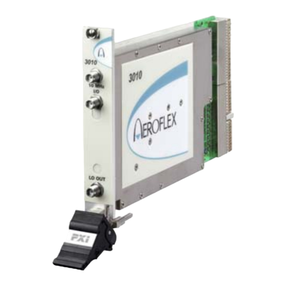
- Page 1 3010 Series RF Synthesizer PXI Module Operating Manual Document no. 46892/637 Issue 7 12 February 2008...
-
Page 2: About This Manual
This manual applies to instruments with software issues of 2.0 and higher. It explains how to set up and configure an Aeroflex 3010 Series RF Synthesizer PXI module. Where necessary, it refers you to the appropriate installation documents that are supplied with the module. -
Page 3: Intended Audience
Driver version This PXI RF module is designed to be used with the latest software driver version supplied on the Aeroflex 3000 Series PXI Modules CD-ROM part no. 46886/028. Operation with earlier versions of driver software may not be supported. -
Page 4: Associated Documentation
Setting up and using the RF digitizer application for Getting Started with 46892/676 3010 Series and 3030 Series modules. afDigitizer Preface Patent protection The 3010 Series RF Synthesizer PXI module is protected by the following patents: GB 2294599 US 5781600 4609881 0125790... -
Page 5: The Pxi Concept
VXI timing and triggering, and VXIplug&play instrument drivers to provide powerful and affordable systems. ® is a registered trademark of Aeroflex International Inc. in the US PXI™ is a registered trademark of the PXI Systems Alliance Windows™, Windows XP™ and Windows NT™ are trademarks of Microsoft Corporation... - Page 6 PREFACE Abbreviations/acronyms Decibels Decibels relative to 1 mW FPGA Field Programmable Gate Array Ground In-System Programming Local Oscillator Peripheral Component Interconnect Pk-Pk Peak-to-Peak PCI eXtensions for Instrumentation Radio Frequency Root Mean Square SDRAM Synchronous Dynamic RAM Soft Front Panel SubMiniature version A (connector) Transistor-Transistor Logic Unit Under Test Voltage-Controlled Oscillator...
-
Page 7: Chapter 1 General Information
Chapter 1 GENERAL INFORMATION Introduction Welcome to the operating manual for the 3010 and 3011 (‘3010 Series’) RF Synthesizer PXI modules. These high-performance frequency synthesizers: • cover the frequency range 1.5 GHz to 3.0 GHz with 1 Hz resolution. •... - Page 8 RF Investigator, also supplied with the module, is an application that provides combined operation of all Aeroflex 3000 Series modules from a single user interface, especially useful for acceptance testing.
-
Page 9: Deliverable Items
GENERAL INFORMATION Deliverable items • 3010 or 3011 RF Synthesizer PXI module • PXI Modules CD-ROM part no. 46886/028, containing soft front panels, drivers, application software, data sheets, getting started and operating manuals for this and other modules in the 3000 Series. •... -
Page 10: Chapter 2 Installation
Chapter 2 INSTALLATION WARNING Initial visual inspection Refer to the 3000 Series Common Installation Guide 46882/663. Handling precautions Refer to the 3000 Series Common Installation Guide 46882/663. Hardware installation Installing the module into the PXI chassis Refer to the 3000 Series Common Installation Guide 46882/663 and Installation Guide for Chassis 46882/667. -
Page 11: Connector Care And Maintenance
INSTALLATION Connector care and maintenance How to connect and torque an SMA connector 1 First, ensure that the mating halves of the connector are correctly aligned. 2 Next, engage the threads of the nut and tighten it by hand, ensuring that the mating halves do not move relative to each other. -
Page 12: Chapter 3 Operation
Chapter 3 OPERATION Front-panel connectors 10 MHz I/O Two SMA I/O sockets in parallel. 10 MHz I/O sockets Input (3010 and 3011) Frequency standard input. 3010 Output (3011 only) Frequency standard output. 10 MHz LO OUT 1.5 to 3 GHz RF output (fixed level, in range −4 to +3 dBm). -
Page 13: 10 Mhz I/O Sockets
OPERATION 10 MHz I/O sockets These are two I/O sockets, wired in parallel, which can be used to ‘loop through’ signals. Both the 3010 and 3011 can accept an external frequency standard input at these sockets. The 3011 can also output a 10 MHz reference from its OCXO on these sockets. The 3010 does not output a 10 MHz signal. -
Page 14: Soft Front Panel (Af3010_Sfp)
Open the AF3010_sfp.exe file; this is in the C:\VXIPNP|WinNT\af3010\ directory on a Windows NT machine, for example. It is also accessible from the Windows Start menu under Programs\Aeroflex\PXI Module Front Panels\AF3010 Front Panel. The soft front panel, similar to that in Fig. 3-2, is displayed. - Page 15 OPERATION Menu Channel setup Trigger Reference setup source C6094 Fig. 3-2 Synthesizer soft front panel...
- Page 16 OPERATION Soft front panel controls Menu bar File Click Exit to close the application. Settings Load and Save allow you to load and save soft front panel configurations from and to your preferred locations. If you did not change the default location when installing the software, it is C:\VXIPNP\WinNT\af3010\settings, and configurations are saved as *.ini files.
- Page 17 OPERATION Options Allows you to enable or disable additional instrument options if you have the appropriate password (available from the Sales Desk). Click Edit. Disabled options are shown grayed out. To enable an option, enter the appropriate password. Click Enable. The enabled option is shown highlighted in green. Click OK.
- Page 18 OPERATION Boot Click Boot to initialize the module and view the Boot Resource window. Resources available for initializing are shown in blue. Select the 3010 or 3011 you want to boot. Note that the Boot Resource window makes no distinction between 3011 (synthesizer module with OCXO) and 3010 (synthesizer module), showing both as ‘3010’.
- Page 19 OPERATION Channel setup Loop b/w Click to toggle between Narrow and Normal. Select Narrow loop bandwidth for better phase noise, or Normal for fastest switching speed consistent with good signal quality. Chan List The Chan List box allows you to select the current channel in non-trigger mode by entering a channel number or by using the up/down arrows.
- Page 20 OPERATION The Edit a range of channels group lets you apply changes to a set of channels simultaneously, speeding up channel setup. • Define start and finish values for address numbers in the Chan range, from: and to: fields. • Insert values and click Set for each field.
- Page 21 OPERATION Reference source 10MHz Reference Mode OCXO Uses the internal 10 MHz OCXO (3011 only). In this mode, the high-stability reference signal is output to the 10 MHz I/O sockets. Internal Uses the internal 10 MHz VCXO (3010 only). There is no output to the 10 MHz I/O sockets.
- Page 22 OPERATION Trigger setup External Trigger Used to control channel-hopping. Mode None Not in hopping mode Advance Step incrementally through the list of 128 channels. The Start and Stop fields let you set a subset of channels. Toggle Toggles between Channel 0 and Channel 1. Receives the channel address from the PXI backplane.
-
Page 23: Driver Export Functions
OPERATION Driver export functions On-line help and functional documentation for driver export functions are available on the CD-ROM supplied with your module. They are installed onto your computer at the same time as the drivers. Driver installation folder Find help and functional documentation in the driver installation folder on your computer. This is typically: C:\vxipnp\winnt\af3010 Help... - Page 24 OPERATION A help file opens at the Contents page: Fig. 3-4 Online help contents — example Hyperlinks from here take you to Introduction Assumptions Error codes Functions listings. 3-13...
-
Page 25: Function Listings
OPERATION Function listings Functions are grouped by type. Click on the hyperlink for details of the function. Each function has a description of its purpose, and may have a list of parameters and return values. An example function is shown below: Fig. -
Page 26: Chapter 4 Brief Technical Description
Chapter 4 BRIEF TECHNICAL DESCRIPTION Introduction The Aeroflex 3010 Series (comprising the 3010 and 3011 modules) is a PXI RF synthesizer covering the frequency range 1500 to 3000 MHz, with a fixed nominal output level of 0 dBm. Its primary purpose is to act as an excitation unit for an RF signal generator (Aeroflex 3020 Series), and as a local oscillator for an RF digitizer (Aeroflex 3030 Series). -
Page 27: Pci Interface
BRIEF TECHNICAL DESCRIPTION PCI interface The PCI interface is implemented in an FPGA device, along with all back-end logic associated with the interface. At power-on the PCI FPGA configures automatically from an on-board ISP PROM. The FPGA I/O is powered from 3.3 V, but is compatible with both 3.3 V and 5 V signaling over the PCI backplane. -
Page 28: Power Supplies
BRIEF TECHNICAL DESCRIPTION Power supplies Adjacent to the backplane connector is a voltage converter. This boosts the 5 V rail from the rack to about 6 V. It also boosts the +12 V rail to about 40 V for use in the VCO and VTF tuning circuits. - Page 29 BRIEF TECHNICAL DESCRIPTION Synthesizer This comprises a 1.5 to 3 GHz fractional-N synthesizer with 1 Hz resolution. It also contains comprehensive frequency reference facilities. The VCO operates from 500 to 667 MHz. The third, fourth and fifth harmonics of this are used to generate the output frequency.
- Page 30 BRIEF TECHNICAL DESCRIPTION The main VCO is differentially tuned. The loop filter voltage is applied to the negative input and a pre-steer voltage is applied to the positive input. The pre-steer voltage is set such that the loop filter voltage is 2.5 V ± 0.5 V. A second steer voltage is applied to the voltage-tuned filter.
- Page 31 BRIEF TECHNICAL DESCRIPTION PRESTEER PULSE GAIN VTBPF HARMONIC TUNE 1.5 to GENERATOR 3 GHz x 3, 4, 5 ¸ ¸2 PROGRAM DIVIDER FRACTIONAL OPTIONAL VCXO/ QUAD DAC OCXO VCXF CONTROL CONTROL EEPROM INTERFACE 10 MHZ REF I/O C5743 Fig. 4-1 Block schematic diagram...
-
Page 32: Chapter 5 Acceptance Testing
Chapter 5 ACCEPTANCE TESTING Introduction The test procedures in this chapter enable you to verify that the 3010/3011 RF Synthesizer is meeting its specified performance. Abbreviations Throughout the chapter, the following abbreviations are used: Unit Under Test Soft Front Panel... -
Page 33: Test Procedures
ACCEPTANCE TESTING Test procedures Each test procedure shows you how to configure the test equipment and then describes how to perform the test. Tables are provided for recording your results. Measurements should fall within the maximum and minimum limits indicated, provided that you use the recommended test equipment and adhere to the test precautions. -
Page 34: Recommended Test Equipment
Minimum specification Example Test parameters Frequency counter 3 GHz Agilent 53181A Frequency accuracy Power meter and 1.5 GHz to 3 GHz Aeroflex 6960B and RF level accuracy sensor 6912 Oscilloscope 10 MHz Tektronix TDS3032 10 MHz reference output Function generator 10 MHz, 0.4–4 V... - Page 35 ACCEPTANCE TESTING Checking that the UUT powers up correctly This test ensures that the 3010 or 3011 powers up in a satisfactory manner and that the internal self-tests do not report any errors. This test assumes that instrument is fitted in a PXI rack and that the supplied installation software is installed on the host controller.
- Page 36 ACCEPTANCE TESTING Carrier frequency test This test checks the module’s frequency locking circuitry. It confirms the correct operation of phase locked loops and dividers. In the case of 3011, the accuracy is determined by the module’s internal reference standard. By using the 3011’s reference output as the reference frequency for the frequency counter, the test limits are ±1 count.
- Page 37 ACCEPTANCE TESTING On the UUT set: 10MHz Reference Mode Internal (3010) 10MHz Reference Mode OCXO (3011) RF Freq (Hz) 1500000000 (may be entered as 1.5e9) Record the frequency measured by the frequency counter against each of the LO frequencies shown in Table 5-1 (3010) or Table 5-2 (3011). Table 5-1 3010 LO frequency results Carrier frequency Minimum (Hz)
- Page 38 ACCEPTANCE TESTING RF output level test The RF output level test ensures correct operation of the signal generator’s level control circuitry. 3010 Power meter 10 MHz 10 MHz I/O LO OUT LO OUT Power sensor C5937 Fig. 5-2 LO output level test setup Connect the test equipment as shown in Fig.
- Page 39 ACCEPTANCE TESTING Record the output level measured by the power meter against each of the LO frequencies shown in Table 5-3. Table 5-3 LO output level results Carrier Minimum Result (dBm) Maximum frequency (dBm) (dBm) −4 1500 MHz −4 1625 MHz −4 1750 MHz −4...
- Page 40 ACCEPTANCE TESTING 10 MHz reference output test — 3011 only This test confirms correct operation of the 10 MHz reference output on the 3011. 3010 10 MHz 10 MHz I/O Oscilloscope LO OUT LO OUT C5938 Fig. 5-3 10 MHz reference output test setup Connect the test equipment as shown in Fig.
- Page 41 ACCEPTANCE TESTING 10 MHz reference input test This test confirms correct operation of the 10 MHz input. 3010 10 MHz 10 MHz I/O Function generator LO OUT LO OUT C5939 Fig. 5-4 10 MHz reference input test setup Connect the test equipment as shown in Fig. 5-4. On the UUT set: 10MHz Reference Mode External...
- Page 42 ACCEPTANCE TESTING Set the function generator to 10 000 100 Hz and repeat (4) above. Set the function generator to 0.4 V pk-pk and repeat (4) above. Table 5-4 10 MHz reference frequency input results Test frequency Test level (Hz) (V pk-pk) 9 999 900 9 999 900...
- Page 43 Licensor. By opening this Software package or commencing to use the software you accept the terms of this Agreement. If you do not agree to the terms of this Agreement please return the Software package unopened to Aeroflex International Limited or do not use the software.
- Page 44 5.3 If during the appropriate Warranty Period the Licensed Software does not conform substantially to the Software Product Descriptions, Data Sheets or Product Specifications Aeroflex will provide: 5.3.1 In the case of Embedded Software and at Aeroflex’s discretion either a fix for the problem or an effective and efficient work- around.
- Page 45 Licensed Software at the commencement of this Agreement. 8.3 Aeroflex shall not be liable to the Licensee for any loss of use or for loss of profits or of contracts arising directly or indirectly out of any such infringement of patent, registered design, trademark or copyright.
- Page 46 This Agreement shall be governed by the laws of England and shall be subject to the exclusive jurisdiction of the English courts. This agreement constitutes the whole Contract between the parties and may be changed only by memorandum signed by both parties. © AEROFLEX INTERNATIONAL LTD 2007...
- Page 47 As we are always seeking to improve our products, the information in this document gives only a general indication of the product capacity, performance and suitability,none of which shall form part of any contract. We reserve the right to make design changes without notice. www.aeroflex.com Email info-test@aeroflex.com November 2005...
Need help?
Do you have a question about the 3010 Series and is the answer not in the manual?
Questions and answers