
Related Manuals for Aeroflex 3065


Summary of Contents for Aeroflex 3065
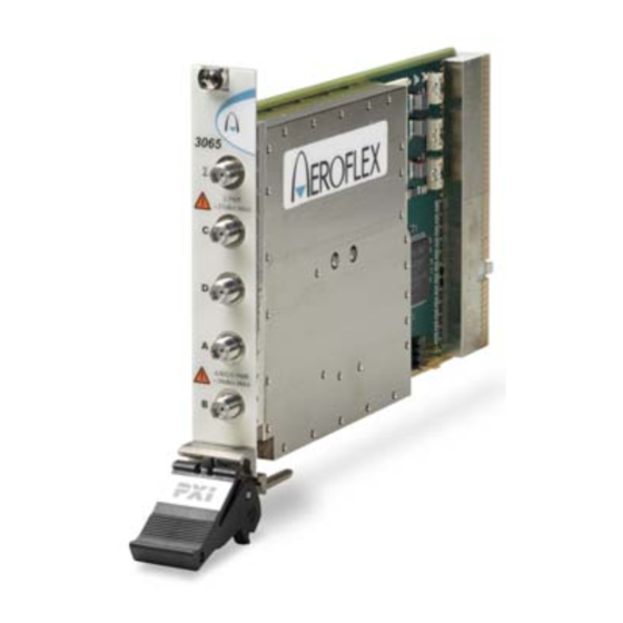
- Page 1 3065 RF Combiner PXI Module Operating Manual Document no. 46892/762 Issue 4 29 October 2007...
-
Page 2: About This Manual
This manual applies to instruments with software issues of 2.0 and higher. This manual explains how to set up and configure an Aeroflex 3065 RF combiner PXI module. Where necessary, it refers you to the appropriate installation documents that are supplied with the module. -
Page 3: Intended Audience
Driver version This PXI RF module is designed to be used with the latest software driver version supplied on the Aeroflex 3000 Series PXI Modules CD-ROM part no. 46886/028. Operation with earlier versions of driver software may not be supported. -
Page 4: Associated Documentation
PREFACE Associated documentation The following documentation covers specific aspects of this equipment: PXI Modules CD-ROM Part no. Compilation containing soft front panels, drivers, 46886/028 application software, data sheets, getting started and operating manuals for this and other modules in the 3000 Series. -
Page 5: The Pxi Concept
VXI timing and triggering, and VXIplug&play instrument drivers to provide powerful and affordable systems. ® is a registered trademark of Aeroflex International Inc. in the US PXI™ is a registered trademark of the PXI Systems Alliance Windows™, Windows XP™ and Windows NT™ are trademarks of Microsoft Corporation... - Page 6 PREFACE Abbreviations/acronyms Decibels Decibels relative to the carrier level Decibels relative to 1 mW Ground Microwave Scalar Analzer Peripheral Component Interconnect Pk-Pk Peak-to-Peak PCI eXtensions for Instrumentation Radio Frequency Root Mean Square Soft Front Panel SubMiniature version A (connector) Unit Under Test VSWR Voltage Standing-Wave Ratio VMEbus Extension for Instrumentation...
-
Page 7: Chapter 1 General Information
Chapter 1 GENERAL INFORMATION Introduction Welcome to the operating manual for the 3065 RF combiner PXI module. This high- performance RF conditioning module features integrated high speed RF switching and a high isolation RF power combiner/splitter and covers the frequency range 250 MHz to 6.0 GHz (usable down to 70 MHz) in a 3U high single-slot PXI module. - Page 8 C to B and A to SUM C to D and A,B to SUM A to D and C,B to SUM RF BLOCK CONTROL 3065 C6104 The 3065 stores its own path loss calibration data, which can be accessed via software calls to the driver.
-
Page 9: Deliverable Items
DVB, port D allows a second RF source to be routed to the unit under test. Software The 3065 is supplied with a VXI PNP driver and soft front panel, and a COM object and a C interface DLL that provide similar functionality to the driver. -
Page 10: Putting Into Storage
GENERAL INFORMATION Cleaning Before commencing any cleaning, switch off the chassis and disconnect it from the supply. You can wipe the front panel of the module using a soft cloth moistened in water, taking care not to wet the connectors. Do not use aerosol or liquid solvent cleaners. Putting into storage If you put the module into storage, ensure that the following conditions are not exceeded: −20 to +70°C (−4 to +158°F) -
Page 11: Chapter 2 Installation
Chapter 2 INSTALLATION WARNING Initial visual inspection Refer to the 3000 Series Common Installation Guide 46882/663. Handling precautions Refer to the 3000 Series Common Installation Guide 46882/663. Hardware installation Installing the module into the PXI chassis Refer to the 3000 Series Common Installation Guide 46882/663 and Installation Guide for Chassis 46882/667. -
Page 12: Connector Care And Maintenance
INSTALLATION Connector care and maintenance How to connect and torque an SMA connector 1 First, ensure that the mating halves of the connector are correctly aligned. 2 Next, engage the threads of the nut and tighten it by hand, ensuring that the mating halves do not move relative to each other. -
Page 13: Chapter 3 Operation
50 Ω. 3065 S PWR S PWR Maximum safe powers +27dBm MAX Σ port: +27 dBm, 3 V dc A, B, C, D ports: +24 dBm A/B/C/D PWR A/B/C/D PWR +24dBm MAX +24dBm MAX C6105 Fig. 3-1 3065 front panel... -
Page 14: Detailed Help Information
Open the AF3060_sfp.exe file; this is in the C:\VXIPNP|WinNT\af3060\ directory on a Windows NT machine, for example. It is also accessible from the Windows Start menu under Programs\Aeroflex\PXI Module Front Panels\AF3060 Front Panel. The soft front panel, similar to that in Fig. 3-2, is displayed. - Page 15 OPERATION Menu bar Routing Path loss Boot C6106 Fig. 3-2 Combiner soft front panel...
- Page 16 Directories lets you choose the locations for your front-panel configuration settings. Options There are currently no options available on the 3065. Help Instrument Information provides the module’s PXI resource code and serial number, revision numbers for driver and PCI, its last calibration date, and associated file information and module build information.
- Page 17 Click Boot to initialize the module and view the Boot Resource window. Resources available for initializing are shown in blue. Select the 3065. Click OK. While you select the boot resource, the indicator is amber. Once the module has initialized, the indicator changes to green in a few seconds.
-
Page 18: Basic Configuration
OPERATION Switching schemes Here are some examples of how you can use the 3065 and other PXI components to provide efficient and economical test setups. Basic configuration 3025 50 W 3025 3035 RF BLOCK CONTROL 3065 C6110 Fig. 3-3 Transceiver test This configuration connects one or two signal sources and a digital analyzer to the unit under test (UUT) for amplifier or mixer intermodulation testing. - Page 19 OPERATION Testing two devices UUT 2 RF BLOCK RF BLOCK CONTROL CONTROL 3065 3065 3025 3025 UUT 1 3035 3035 RF BLOCK RF BLOCK CONTROL CONTROL 3065 3065 C6111 Configuration 1 Configuration 2 Fig. 3-4 Dual transceiver test These two configurations let you use a single signal source and digital analyzer to test two...
- Page 20 UUT 1 50 W UUT 2 UUT 3 3035 RF BLOCK RF BLOCK CONTROL CONTROL 3065 3065 C6112 Fig. 3-5 Triple transceiver test This configuration lets you connect three devices under test to a single signal source and digital analyzer.
- Page 21 3035 RF BLOCK CONTROL 3065 C6113 Fig. 3-6 Cellular and non-cellular transceiver test This configuration lets you feed both cellular and non-cellular (for example, GSP or DVB) signals to the UUT’s independent RF connection points, so that parallel testing is possible.
-
Page 22: Driver Export Functions
Help files are provided in three formats: af3060.doc 3065 function documentation Text file af3060.hlp 3065 Visual BASIC function reference Windows Help file format af3060_C.hlp 3065 C language function reference We recommend that you use the C or Visual Basic formats as these are easier to navigate. - Page 23 OPERATION The file opens at the Contents page: Fig. 3-7 Online help contents — example Hyperlinks from here take you to Introduction Assumptions Error codes Functions listings. 3-11...
- Page 24 OPERATION Functions listings Functions are grouped by type. Click on the hyperlink for details of the function. Each function has a description of its purpose, and may have a list of parameters and return values. Fig. 3-8 Function description — example 3-12...
-
Page 25: Chapter 4 Brief Technical Description
RF switch control and combiner path calibration information is communicated via the PXI backplane. The 3065 module consists of an RF block and a PCI interface board; a description of each is given below. RF block The RF block performs the signal combination and switching between ports A, B, C and Σ,... -
Page 26: Pci Interface
BRIEF TECHNICAL DESCRIPTION PCI interface The PCI interface enables inter-module communication via the PCI bus and provides control and power signals to the 3065. An EEPROM stores module-related calibration data. RF BLOCK CONTROL 3065 C6104 Fig. 4-1 Block schematic diagram... -
Page 27: Chapter 5 Acceptance Testing
Chapter 5 ACCEPTANCE TESTING Introduction The test procedures in this chapter enable you to verify that the 3065 RF Combiner is meeting its specified performance. Abbreviations Throughout the chapter, the following abbreviations are used: Unit Under Test Soft Front Panel... - Page 28 ACCEPTANCE TESTING Controlling the UUT Control of the UUT (unit under test) is by the SFP (soft front panel) supplied on the CD−ROM (part no. 46886/028). Follow the instructions provided in the 3000 Series Common Installation Guide (part no. 46882/663) to ensure that this software is correctly installed. Each test procedure relies on the module being set to its power−up conditions.
-
Page 29: Recommended Test Equipment
Example Test parameters Signal generator 250 MHz to 6 GHz Aeroflex 3416 Insertion loss Power meter and 250 MHz to 6 GHz Aeroflex 6960B and 6924 Insertion loss sensor Power splitter 6 GHz Agilent 11667B Insertion loss Spectrum analyzer 6 GHz... -
Page 30: Test Precautions
ACCEPTANCE TESTING Test precautions To ensure minimum errors and uncertainties when making measurements, it is important to observe the following precautions: Always use recently calibrated test equipment, with any correction figures taken into • account, so as to establish a known traceable limit of performance uncertainty. This uncertainty must be allowed for in determining the accuracy of measurements. - Page 31 Checking that the UUT powers up correctly This test ensures that the 3065 powers up in a satisfactory manner and that the internal self- tests do not report any errors. This test assumes that instrument is fitted in a PXI chassis and that the supplied installation software is installed on the host controller.
- Page 32 A and B or B and C or A and D or C and D • the isolation between ports A and B, A and C, or B and C with the 3065 set to A,B,C to Σ •...
- Page 33 ACCEPTANCE TESTING 3065 S PWR S PWR +27dBm MAX Power sensor Signal generator A/B/C/D PWR A/B/C/D PWR Power meter 2 +24dBm MAX +24dBm MAX EXT I EXT AM SWEEP ON/OFF 50 / ANALOG 100k ON/OFF RF OUTPUT EXT Q EXT FM <TAB>...
-
Page 34: Insertion Loss
ACCEPTANCE TESTING Insertion loss A–Σ Connect the test equipment as shown in Fig. 5-1 and terminate the unused ports with 50 ohm terminations. On the UUT set: A,B,C to SUM. On the signal generator set: Carrier Frequency 250 MHz RF Level 0 dBm Record the difference in the level measured between power meter 1 and power meter 2 in Table 5-1. - Page 35 ACCEPTANCE TESTING A–B 10 Connect the signal generator/splitter/power meter 1 to the UUT A port and power meter 2 to the UUT B port and terminate the unused ports with 50 ohm terminations. 11 On the UUT set: A to B. C to SUM. 12 Repeat (3) and (4) at the frequencies shown in Table 5-3.
- Page 36 ACCEPTANCE TESTING C–D 19 Connect the signal generator/splitter/power meter 1 to the UUT C port and power meter 2 to the UUT D port and terminate the unused ports with 50 ohm terminations. 20 On the UUT set: A to B. C to D. 21 Repeat (3) and (4) at the frequencies shown in Table 5-4.
- Page 37 ACCEPTANCE TESTING Table 5-1 Insertion loss results, A–∑, B–∑ Frequency A–∑ B–∑ Limit (dB) (MHz) result (dB) result (dB) <15.5 <15.5 <15.5 1000 <15.5 1250 <15.5 1500 <15.5 1750 <15.5 2000 <15.5 2250 <15.5 2500 <15.5 2700 <15.5 3000 <17.5 4000 <17.5 5000...
- Page 38 ACCEPTANCE TESTING Table 5-2 Insertion loss results, C–∑ Frequency C–∑ Limit (dB) (MHz) result (dB) <16 <16 <16 1000 <16 1250 <16 1500 <16 1750 <16 2000 <16 2250 <16 2500 <16 2700 <16 3000 <16 4000 <16 5000 <16 6000 <16 5−12...
- Page 39 ACCEPTANCE TESTING Table 5-3 Insertion loss A–B, B–C Frequency A–B B–C Limit (dB) (MHz) result (dB) result (dB) <3 <3 <3 1000 <3 1250 <3 1500 <3 1750 <3 2000 <3 2250 <3 2500 <3 2700 <3 3000 <5 4000 <5 5000 <5...
- Page 40 ACCEPTANCE TESTING Table 5-4 Insertion loss A–D, C–D Frequency A–D C–D Limit (dB) (MHz) result (dB) result (dB) <3 <3 <3 1000 <3 1250 <3 1500 <3 1750 <3 2000 <3 2250 <3 2500 <3 2700 <3 3000 <5 4000 <5 5000 <5...
- Page 41 ACCEPTANCE TESTING Isolation 3065 Spectrum analyzer S PWR S PWR +27dBm MAX Signal generator A/B/C/D PWR A/B/C/D PWR +24dBm MAX +24dBm MAX EXT I EXT AM SWEEP ON/OFF 50 / ANALOG ON/OFF 100k RF OUTPUT EXT Q EXT FM SOURCE <TAB>...
- Page 42 ACCEPTANCE TESTING A–B Connect the test equipment as shown in Fig. 5-2 and terminate the other ports with 50 ohm terminations. On the UUT set: A,B,C to SUM. On the signal generator set: Carrier Frequency 250 MHz RF Level 0 dBm On the spectrum analyzer set: Carrier Frequency 250 MHz...
- Page 43 ACCEPTANCE TESTING B–D 11 Connect the signal generator/splitter/power meter to the UUT B port, the spectrum analyzer to the D port, and terminate the other ports. 12 Repeat (3) to (5) at the frequencies in Table 5-5. A–D 13 Connect the signal generator/splitter/power meter to the UUT A port, the spectrum analyzer to the D port and terminate the other ports.
- Page 44 ACCEPTANCE TESTING Table 5-5 Isolation results (all ports except B–C) Frequency A–B A–C B–D A–D C–D D–SUM Limit (dB) (MHz) result (dB) result (dB) result (dB) result (dB) result (dB) result (dB) >35 >35 >35 1000 >35 1250 >35 1500 >35 1750 >35...
- Page 45 ACCEPTANCE TESTING Table 5-6 Isolation results B–C Frequency B–C Limit (dB) (MHz) result (dB) >35 >35 >35 1000 >35 1250 >35 1500 >35 1750 >35 2000 >35 2250 >32 2500 >32 2700 >32 3000 >32 4000 >32 5000 >32 6000 >32 5−19...
-
Page 46: Return Loss
ACCEPTANCE TESTING Return loss 3065 S PWR S PWR +27dBm MAX Microwave scalar analyzer A/B/C/D PWR A/B/C/D PWR +24dBm MAX +24dBm MAX INPUT A SIGNAL SOURCE OUTPUT Open/short circuit INPUT DETECTED TEST PORT OUTPUT (connect directly to on UUT) Autotester C6109 Fig. - Page 47 ACCEPTANCE TESTING A, B, C to Σ Port Σ Connect the test equipment as shown in Fig. 5-3 and terminate the unused ports with 50 ohm terminations. On the UUT set: A,B,C to SUM. On the microwave scalar analyzer (MSA) define the source conditions as follows: [PRESET] [Full] [SOURCE]...
- Page 48 ACCEPTANCE TESTING Port A 11 Connect the autotester to the A port, terminate the unused ports with 50 ohm terminations and repeat (10) above using Table 5-8. Port B 12 Connect the autotester to the B port, terminate the unused ports with 50 ohm terminations and repeat (10) above using Table 5-9.
- Page 49 ACCEPTANCE TESTING Ports B and C 19 On the UUT set: B to C. A to D. 20 Connect the autotester to the B port, terminate the C port with a 50 ohm termination and repeat (10) above using Table 5-10. 21 Connect the autotester to the C port, terminate the B port with a 50 ohm termination and repeat (10) above using Table 5-10.
- Page 50 ACCEPTANCE TESTING Table 5-7 Port Σ return loss result Σ Frequency Limit (dB) (MHz) Result (dB) In range 250 MHz to >20 2.7 GHz: In range 2.7 GHz to >18 5 GHz: In range 5 GHz to >16 6 GHz: Table 5-8 Port A return loss result Frequency Limit (dB)
- Page 51 ACCEPTANCE TESTING Table 5-9 Ports B, C and D return loss result Frequency Limit (dB) (MHz) Result (dB) Result (dB) Result (dB) In range 250 MHz to >14 2.7 GHz: typ. 17 In range 2.7 GHz to >11 6 GHz: typ.
- Page 52 Licensor. By opening this Software package or commencing to use the software you accept the terms of this Agreement. If you do not agree to the terms of this Agreement please return the Software package unopened to Aeroflex International Limited or do not use the software.
- Page 53 5.3 If during the appropriate Warranty Period the Licensed Software does not conform substantially to the Software Product Descriptions, Data Sheets or Product Specifications Aeroflex will provide: 5.3.1 In the case of Embedded Software and at Aeroflex’s discretion either a fix for the problem or an effective and efficient work- around.
- Page 54 Licensed Software at the commencement of this Agreement. 8.3 Aeroflex shall not be liable to the Licensee for any loss of use or for loss of profits or of contracts arising directly or indirectly out of any such infringement of patent, registered design, trademark or copyright.
- Page 55 This Agreement shall be governed by the laws of England and shall be subject to the exclusive jurisdiction of the English courts. This agreement constitutes the whole Contract between the parties and may be changed only by memorandum signed by both parties. © AEROFLEX INTERNATIONAL LTD 2007...
- Page 56 As we are always seeking to improve our products, the information in this document gives only a general indication of the product capacity, performance and suitability,none of which shall form part of any contract. We reserve the right to make design changes without notice. www.aeroflex.com Email info-test@aeroflex.com November 2005...
Need help?
Do you have a question about the 3065 and is the answer not in the manual?
Questions and answers