Table of Contents

Subscribe to Our Youtube Channel
Related Manuals for Samson RINGO 3595


Summary of Contents for Samson RINGO 3595
- Page 1 EB 8079 EN Translation of original instructions Type 3595 Valve with Type 3271 Actuator Type 3595 Valve · ANSI version For combination with actuators, such as Pneumatic Actuator 3276 or Type 3271 Pneumatic Actuator Edition June 2024...
- Page 2 Note on these mounting and operating instructions These mounting and operating instructions assist you in mounting and operating the device safely. The instructions are binding for handling RINGO devices. The images shown in these instructions are for illustration purposes only. The actual product may vary. Î...
-
Page 3: Table Of Contents
Contents Safety instructions and measures ..............1-1 Notes on possible severe personal injury ............1-4 Notes on possible personal injury ..............1-5 Notes on possible property damage .............1-7 Markings on the device ................2-1 Valve nameplate ..................2-1 Actuator nameplate ..................2-1 Design and principle of operation ...............3-1 Fail-safe action ...................3-3 Versions .....................3-4 Additional fittings ..................3-4 Technical data ....................3-5 Shipment and on-site transport ..............4-1 Accepting the delivered goods ..............4-1... - Page 4 Contents Malfunctions ....................8-1 Troubleshooting ..................8-1 Emergency action ..................8-3 Servicing....................9-1 Periodic testing ...................9-3 Service work preparations ................9-3 Installing the valve after service work ............9-4 Service work....................9-4 9.4.1 Replacing the gaskets ..................9-4 9.4.2 Replacing the packing .................9-5 9.4.3 Replacing the bellows seal ................9-6 9.4.4 Lapping the seat and plug ................9-7 Ordering spare parts and operating supplies ..........9-8...
-
Page 5: Safety Instructions And Measures
The Type 3595 Globe or Angle Valve in combination with an actuator (e.g. Pneumatic Actu- ator 3276 or SAMSON Type 3271 Pneumatic Actuator) is designed to regulate the flow rate, pressure or temperature of liquids, gases or vapors. The valve is suitable for throttling and on/off service in the oil and gas industry as well as for high-temperature applications in power plants. - Page 6 (see associated actuator documentation). For example, when the valve is combined with a SAMSON Type 3271 Pneumatic Actuator, the valve moves to a certain fail- safe position (see the 'Design and principle of operation' chapter) upon supply air or control signal failure.
- Page 7 Safety instructions and measures Furthermore, the intended purpose may involve the use of the device in hazardous areas. In this case, all work on the control valve must only be performed when no potentially explosive atmosphere is present. Hazards resulting from the special working conditions at the installation site of the valve must be identified in a risk assessment and prevented through the corresponding safety instruc- tions drawn up by the operator.
-
Page 8: Notes On Possible Severe Personal Injury
Safety instructions and measures Referenced documents The following documents apply in addition to these mounting and operating instructions: − Mounting and operating instructions for mounted actuator, e.g. u EB 8318 for Pneumat- ic Actuator 3276 or u EB 8310-X for Type 3271 Pneumatic Actuator − Mounting and operating instructions for mounted valve accessories (positioner, solenoid valve etc.) −... -
Page 9: Notes On Possible Personal Injury
Safety instructions and measures 1.2 Notes on possible personal injury WARNING Risk of burn injuries due to hot or cold components and pipelines. Depending on the process medium, valve components and pipelines may get very hot or cold and cause burn injuries. Î Allow components and pipelines to cool down or warm up to the ambient tempera- ture. Î... - Page 10 Safety instructions and measures WARNING Crush hazard arising from moving parts. The control valve contains moving parts (actuator and plug stem), which can injure hands or fingers if inserted into the valve. Î Do not insert hands or finger into the yoke while the air supply is connected to the actuator.
-
Page 11: Notes On Possible Property Damage
Safety instructions and measures WARNING Exposure to hazardous substances poses a serious risk to health. Certain lubricants and cleaning agents are classified as hazardous substances. These substances have a special label and a material safety data sheet (MSDS) issued by the manufacturer. Î Make sure that an MSDS is available for any hazardous substance used. If neces- sary, contact the manufacturer to obtain an MSDS. - Page 12 Safety instructions and measures NOTICE Risk of leakage and valve damage due to over- or under-torquing. Observe the specified torques when tightening control valve components. Excessive tightening torques lead to parts wearing out more quickly. Parts that are too loose may cause leakage. Î Observe the specified tightening torques (see the 'Tightening torques, lubricants and tools' chapter in the Appendix).
-
Page 13: Markings On The Device
Markings on the device 2 Markings on the device 2.1 Valve nameplate The valve nameplate includes the key specifi- cations of the valve, e.g.: − Manufacturer specifications − Type designation − Nominal size − Pressure rating − Date of manufacture − Serial number It is located on the valve body. 2.2 Actuator nameplate See associated actuator documentation. - Page 14 EB 8079 EN...
-
Page 15: Design And Principle Of Operation
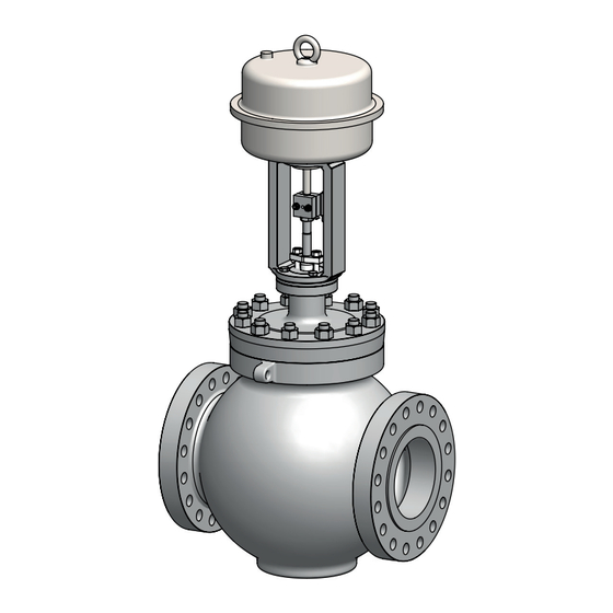
Design and principle of operation 3 Design and principle of oper- The plug stem in the valve bonnet is sealed by either a PTFE or graphite packing, which ation is either self adjusting or can be adjusted manually. See Fig. 3-1 The valve has a clamped-in seat. The seat is Valve style and actuator inserted into the seat bridge. - Page 16 Design and principle of operation Fig. 3-1: Type 3595 Valve with Type 3271 Actuator 3-2 EB 8079 EN...
-
Page 17: Fail-Safe Action
SAMSON Type 3271 Pneumatic Actuator, the valve has two differ- ent fail-safe positions: The direction of action of the SAMSON − Actuator stem extends (FA) Type 3271 Pneumatic Actuator can be re- When the signal pressure is reduced or versed, if required. -
Page 18: Versions
Design and principle of operation 3.2 Versions Bypass and shut-off valves RINGO recommends installing a shut-off Actuators valve both upstream of the strainer and In these instructions, the preferable combina- downstream of the valve and installing a by- tion with a Pneumatic Actuator 3276 or a pass line. The bypass ensures that the plant Type 3271 Pneumatic Actuator is described. -
Page 19: Technical Data
Design and principle of operation 3.4 Technical data Noise emissions RINGO is unable to make general statements The nameplates on the valve and actuator about noise emissions. The noise emissions provide information on the control valve ver- depend on the valve version (e.g. with cage), sion. - Page 20 Design and principle of operation Table 3-2: Materials Type 3595 Globe Valve Cast body Forged body Cast steel or A216 WCB A105 forged steel High- Standard temperature A217 WC6 A182 F11 materials cast steel or A217 WC9 A182 F22 Valve forged steel body and Stainless steel A351 CF8M A182 F316 valve bonnet A351-CK3MCuN A182 F44 Duplex steel A890 Gr. 4A CD3MN A182 F51 Special...
- Page 21 Design and principle of operation Nominal size NPS Dimension Pressure rating ¾ 1½ 7.76 8.54 10.91 12.76 Class 150 to 600 8.66 8.66 9.49 9.96 12.13 12.32 Class 900 Height H4 to 1500 10.04 10.04 10.83 11.54 12.87 14.53 Class 2500 Height H3 3.94 3.94 3.94 3.94 4.92 5.91 Class 150 for Actua- to 2500...
- Page 22 Design and principle of operation Nominal size NPS Dimension Pressure rating 15.35 17.64 21.02 22.87 25.2 27.09 Class 150 to 300 15.24 17.28 22.48 23.62 25.2 26.89 Class 600 14.53 16.65 24.13 24.25 23.23 26.38 Height H4 Class 900 16.57 17.8 24.13 22.72 25.71 29.53 Class 1500 17.28 21.26 26.89 30.35 34.72 39.02...
- Page 23 Design and principle of operation Table 3-4: Dimensions of Type 3595 Valve · Flanged valve body version Table 3-4.1: NPS ¾ to 4 · Dimensions in inches and mm Nominal size NPS ¾ 1½ Flange form Dimension Pressure rating 7.24 – 7.24 – 8.74 – 10.00 – 11.73 – 13.86 –...
- Page 24 Design and principle of operation Table 3-4.2: NPS 6 to 16 · Dimensions in inches and mm Nominal size NPS Flange form Dimension Pressure rating 17.76 – 21.38 – 26.50 – 29.02 – 35.00 – 40.00 – Class 150 – – – – – 1016 – 18.62 – 22.36 –...
- Page 25 Design and principle of operation Nominal size NPS 15.35 17.64 21.02 22.87 25.2 27.09 Class 150 to 300 15.24 17.28 22.48 23.62 25.2 26.89 Class 600 14.53 16.65 24.13 24.25 23.23 26.38 Height H4 Class 900 16.57 17.8 24.13 22.72 25.71 29.53 Class 1500 17.28 21.26 26.89 30.35 34.72 39.02 Class 2500 Height H3 7.87...
- Page 26 Design and principle of operation Table 3-6: Dimensions for Pneumatic Actuator 3276 Version (effective diaphragm area) Dimension 330 (387 cm²) 350 (645 cm²) 380 (1032 cm²) 390 (1032 cm²) 17.09 27.17 27.91 34.02 Actuator stem extends 17.6 27.76 31.85 36.65 Actuator stem retracts 11.50 15.12 17.99 17.99 ØD 9.84 19.69 19.69 19.69 ØD1 6.65 11.14 11.14 15.83 Actuator stem extends...
- Page 27 Design and principle of operation Dimensional drawings ØD ØD ØD1 Type 3595 Globe Valve with Pneumatic Type 3595 Globe Valve with Type 3271 Actuator 3276 · Body with welding ends or Pneumatic Actuator · Flanged body welding-neck ends EB 8079 EN 3-13...
- Page 28 3-14 EB 8079 EN...
-
Page 29: Shipment And On-Site Transport
Shipment and on-site transport 4 Shipment and on-site trans- Î Leave the control valve in its transport container or on the pallet to transport it port on site. The work described in this chapter is to be Î Do not remove the protective caps from performed only by personnel appropriately the inlet and outlet until immediately be- qualified to carry out such tasks. -
Page 30: Transporting The Valve
Transport instructions A swivel hoist can be screwed into − Protect the control valve against external SAMSON actuators with a female thread on influences (e.g. impact). the top diaphragm case in place of the − Do not damage the corrosion protection eyebolt (see associated actuator (paint, surface coatings). - Page 31 Shipment and on-site transport − The permissible transportation tempera- ture of standard control valves is –20 to +65 °C/–4 to +149 °F. Note Contact our after-sales service for the trans- portation temperatures of other valve ver- sions. Fig. 4-1: Lifting points on the control valve: with flanges (left) and with welding ends or welding-neck ends (right) EB 8079 EN 4-3...
-
Page 32: Lifting The Valve
Shipment and on-site transport 4.3.2 Lifting the valve tects the control valve from tilting while being lifted. Before lifting the control valve, tighten the sling. WARNING Lifting the control valve Risk of personal injury and valve damage due to incorrect lifting of the valve. 1. Attach one sling (or other suitable lifting Special lifting conditions apply to valves in tackle) to each flange or welding end of Class 900 and higher as well as ≥NPS 24. -
Page 33: Storage
− Store elastomers away from lubricants, storage conditions regularly. chemicals, solutions and fuels. Storage instructions − Protect the control valve against external SAMSON's After-sales Service can provide influences (e.g. impact). more detailed storage instructions on re- quest. − Secure the valve in the stored position against slipping or tipping over. - Page 34 EB 8079 EN...
-
Page 35: Installation
Installation 5 Installation Î Install the valve allowing sufficient space to remove the actuator and valve or to The work described in this chapter is to be perform service work on them. performed only by personnel appropriately Mounting position qualified to carry out such tasks. Generally, RINGO recommends installing 5.1 Installation conditions the valve with the actuator upright and on... - Page 36 Fig. 5-1. vices. They ensure that any exhaust air that Î Contact SAMSON's After-sales Service forms can be vented to the atmosphere (to for additional points of attachment. avoid excess pressure in the device). Further- more, the vent plugs allow air intake to pre- vent a vacuum from forming in the device.
- Page 37 Installation Table 5-1: Inlet and outlet lengths Flow rate Inlet length Outlet length a x NPS b x NPS State of process Valve conditions Inlet length a Outlet length b 1) 2) medium Ma ≤ 0.3 0.3 ≤ Ma ≤ 0.7 Ma ≤ 0.3 3) 0.3 ≤ Ma ≤ 0.7 3) Vapor Wet steam (percentage of condensate > 5 %) Free of cavitation/w < 10 m/s Cavitation producing noise/w ≤ 3 m/s Cavitation producing Liquid...
-
Page 38: Preparation For Installation
Installation 5.2 Preparation for installation Note Before installation, make sure the following The plant operator is responsible for clean- conditions are met: ing the pipelines in the plant. − The valve is clean. Î For steam applications, dry the pipelines. −... -
Page 39: Mounting The Actuator Onto The Valve
Installation 5.3.2 Installing the valve into NOTICE the pipeline Risk of valve damage due to the use of un- suitable tools. Î Only use tools approved by RINGO (see NOTICE the 'Tightening torques, lubricants and Risk of valve damage due to work being tools' chapter in the Appendix). -
Page 40: Testing The Installed Valve
Installation row on the valve indicates the direction Î Drain the process medium from the plant of flow. sections affected as well as from the valve. 5. Make sure that the correct flange gaskets are used. 6. Bolt the pipe to the valve free of stress. WARNING 7. -
Page 41: Leakage
Installation 5.4.1 Leakage Î Do not impede the movement of the actu- ator and plug stem by inserting objects The plant operator is responsible for per- into the yoke. forming the leak test and selecting the test Î Before unblocking the actuator and plug method. -
Page 42: Travel Motion
Installation 5.4.4 Pressure test 1. Tighten the nuts on the packing gland clockwise in a crisscross pattern until the The plant operator is responsible for per- packing seals the valve. forming the pressure test. 2. Open and close the valve several times. 3. -
Page 43: Start-Up
Start-up 6 Start-up Î Wear hearing protection when working near the valve. The work described in this chapter is to be performed only by personnel appropriately qualified to carry out such tasks. WARNING WARNING Crush hazard arising from actuator and WARNING plug stem moving. - Page 44 Start-up Before start-up or putting the valve back into service, make sure the following conditions are met: − The control valve is properly installed in the pipeline (see the 'Installation' chap- ter). − The leak and function tests have been completed successfully (see the 'Testing the installed valve' chapter).
-
Page 45: Operation
Operation 7 Operation Î Wear hearing protection when working near the valve. Immediately after completing start-up or placing the valve back into service (see the 'Start-up' chapter), the valve is ready for WARNING WARNING use. Crush hazard arising from actuator and plug stem moving. -
Page 46: Normal Operation
Operation 7.1 Normal operation The handwheel of valves with actuators fitted with a handwheel must be in the neutral po- sition during normal operation. 7.2 Manual operation Valves with actuators fitted with a handwheel can be manually closed or opened in the event of failure of the auxiliary energy sup- ply. -
Page 47: Malfunctions
Malfunctions 8 Malfunctions 8.1 Troubleshooting Malfunction Possible reasons Recommended action Actuator and plug stem Actuator is blocked. Put the control valve out of operation (see the does not move on 'Decommissioning' chapter) and remove the demand. blockage. WARNING! A blocked actuator or plug stem (e.g. due to seizing up after remaining in the same position for a long time) can suddenly start to move uncontrollably. - Page 48 Malfunctions Malfunction Possible reasons Recommended action Increased flow through Dirt or other foreign Shut off the section of the pipeline and flush the closed valve (seat particles deposited valve. leakage) between the seat and plug. Faces on the seat ring See section 'Lapping the seat and plug' in the and plug are slightly 'Servicing' chapter.
-
Page 49: Emergency Action
Malfunctions 8.2 Emergency action Plant operators are responsible for emergen- cy action to be taken in the plant. In the event of a valve malfunction: 1. Close the shut-off valves upstream and downstream of the control valve to stop the process medium from flowing through the valve. - Page 50 EB 8079 EN...
-
Page 51: Servicing
Servicing 9 Servicing Î Allow components and pipelines to cool down or warm up to the ambient tem- The work described in this chapter is to be perature. performed only by personnel appropriately Î Wear protective clothing and safety qualified to carry out such tasks. gloves. - Page 52 Servicing WARNING WARNING WARNING Crush hazard arising from actuator and Risk of personal injury due to the pre- plug stem moving. loaded actuator springs. Î Do not insert hands or finger into the Valves in combination with pneumatic actua- yoke while the air supply is connected to tors with preloaded springs are under ten- the actuator.
-
Page 53: Periodic Testing
Servicing 9.1 Periodic testing NOTICE Risk of valve damage due to the use of un- Depending on the operating conditions, suitable tools. check the valve at certain intervals to prevent Î Only use tools approved by RINGO (see possible failure before it can occur. Plant op- the 'Tightening torques, lubricants and erators are responsible for drawing up an tools' chapter in the Appendix). -
Page 54: Installing The Valve After Service Work
Servicing 7. Take the cage (two-pieced, if applicable) − Make sure the valve bonnet is and seat ring out of the valve body. aligned so that the packing gland is at a right angle to the valve's direc- The following service work can be per- tion of flow. -
Page 55: Replacing The Packing
Servicing 2. Insert new gaskets, observing the proper alignment and position/centering of each gasket (see Fig. 9-1). Gasket U-ring Fig. 9-2: Aligning the U-ring 9.4.2 Replacing the packing 1. Unthread the nuts of the packing gland Gasket from the valve bonnet. 2. Remove the packing gland and packing follower. -
Page 56: Replacing The Bellows Seal
Servicing 5. Clean the packing chamber thoroughly. Double packing Single packing 6. Renew damaged parts. 7. Apply a suitable lubricant to all the pack- Packing ing parts and to the plug stem (see the gland 'Tightening torques, lubricants and tools' Stud Packing chapter in the Appendix). -
Page 57: Lapping The Seat And Plug
Servicing ing a suitable tool. Observe the proper Î Contact SAMSON's After-sales Service sequence (see Fig. 9-3). Department when reworking is required. 7. Carefully slide the packing follower Necessary conditions for lapping downwards over the plug stem. In addition to preparation before performing 8. -
Page 58: Ordering Spare Parts And Operating Supplies
Servicing plug. This leads to a changed flow rate and plug stem and press the plug by hand in- changes the control characteristics of the to the seat. Apply compressed air to the valve as a result. inlet side of the valve. Repeat the lapping Î... - Page 59 Servicing Spare parts See the Appendix for details on spare parts. Lubricants See the Appendix for details on suitable lu- bricants. Tools See the Appendix for details on suitable tools. EB 8079 EN...
- Page 60 9-10 EB 8079 EN...
-
Page 61: Decommissioning
Decommissioning 10 Decommissioning WARNING The work described in this chapter is to be Risk of personal injury due to pressurized performed only by personnel appropriately components and as a result of process me- qualified to carry out such tasks. dium being discharged. Î... - Page 62 Decommissioning (e.g. due to seizing up after remaining in 2. Completely drain the pipelines and the same position for a long time), re- valve. lease any stored energy in the actuator 3. Disconnect and lock the pneumatic air (e.g. spring compression). See associat- supply to depressurize the actuator.
-
Page 63: Removal
Removal 11 Removal WARNING WARNING The work described in this chapter is to be Risk of personal injury due to residual pro- performed only by personnel appropriately cess medium in the valve. qualified to carry out such tasks. While working on the valve, residual me- dium can flow out of the valve and, depend- ing on its properties, cause personal injury, WARNING... -
Page 64: Removing The Actuator From The Valve
Removal 2. Unbolt the flanged joint. 3. Remove the valve from the pipeline (see the 'Shipment and on-site transport' chapter). b) Version with welding ends 1. Support the valve to hold it in place when separated from the pipeline (see the 'Shipment and on-site transport' chapter). -
Page 65: Repairs
Repairs 12 Repairs The declaration form can be downloaded from our website at u .www.samsongroup. If the valve does not function properly ac- com > Service > After-sales Service > cording to how it was originally sized or Returning goods does not function at all, it is defective and must be repaired or exchanged. - Page 66 12-2 EB 8079 EN...
-
Page 67: Disposal
Disposal 13 Disposal Î Observe local, national and internation- al refuse regulations. Î Do not dispose of components, lubricants and hazardous substances together with your household waste. EB 8079 EN 13-1... - Page 68 13-2 EB 8079 EN...
-
Page 69: Certificates
Certificates 14 Certificates The following declaration is included on the next pages: − Declaration of conformity in compliance with Pressure Equipment Directive 2014/68/EU The certificates shown were up to date at the time of publishing. Other optional certificates are available on request. - Page 70 In accordance with the requirements of the Pressure Equipment Directive 2014/68/EU This is to certify that the Quality Management System of RINGO VALVULAS, S.L. (SAMSON – RINGO) Pol. Industrial Empresarium C/ Romero nº 6 y 8 50720 – La Cartuja (ZARAGOZA) -Spain...
- Page 71 EU CERTIFICATE SCHEDULE 0094/PED/MAD/0132 ENG In accordance with the requirements of the Pressure Equipment Directive 2014/68/EU. Design Size Rating Product (s) Model Standard/ Materials Range Range Code 1.0426 (EN 10222-2), 1.0460 (EN 10273), 1.0619 (EN 10213), 1.0625 (EN 10213), 1.0426 (EN 10222-2), 1.0460 (EN 10273), 1.0619 (EN 10213), 1.0625 (EN 1.0426 (EN 10222-2), 1.0460 (EN 10273), 1.0619 (EN 10213), 1.0625 (EN...
- Page 72 EU CERTIFICATE SCHEDULE 0094/PED/MAD/0132 ENG In accordance with the requirements of the Pressure Equipment Directive 2014/68/EU. Design Size Rating Product (s) Model Standard/ Materials Range Range Code A216 (WCB/WCC), A182 (Gr.: F1/F5/F5a/F9/F11/F22/F44/F51/F53/F 91/F304/F304L/F316/F316H/F316L/F3 21/F347/F347H), A240 316, A217 (C5/C12A/WC1/WC6/WC9), A350 (LF2/LF3), A351 (CD4MCu/CF3/CF3M/CF8/CF8C/CF8M/ CK3MCuN),...
- Page 73 EU CERTIFICATE SCHEDULE 0094/PED/MAD/0132 ENG In accordance with the requirements of the Pressure Equipment Directive 2014/68/EU. Design Size Rating Product (s) Model Standard/ Materials Range Range Code 1.0426 (EN 10222-2), 1.0460 (EN 10273), 1.0619 (EN 10213), 1.0625 (EN 10213), 1.4308 (EN 10213), 1.4401 (EN 10222-5), 1.4404 (EN 10222-5), 1.4408 (EN 10213), 1.4409 (EN 10213), 1.4541 (EN 10222-5), 1.4550 (EN 10222-5),...
- Page 74 EU CERTIFICATE SCHEDULE 0094/PED/MAD/0132 ENG In accordance with the requirements of the Pressure Equipment Directive 2014/68/EU. Design Size Rating Product (s) Model Standard/ Materials Range Range Code 21/F347/F347H), A240 316, A217 (C5/C12A/WC1/WC6/WC9), A350 (LF2/LF3), A351 (CD4MCu/CF3/CF3M/CF8/CF8C/CF8M/ CK3MCuN), A352 (LC1/LC2/LC3/LCB/LCC), A453 Gr. 660B, A479 (T304/T304L/T316/T316L/T321), A494...
- Page 75 EU CERTIFICATE SCHEDULE 0094/PED/MAD/0132 ENG In accordance with the requirements of the Pressure Equipment Directive 2014/68/EU. Design Size Rating Product (s) Model Standard/ Materials Range Range Code (EN 1.0426 (EN 10222-2), 1.0460 (EN 10273), 1.0619 (EN 10213), 1.0625 (EN 10213), 1.4308 (EN 10213), 1.4401 (EN 10222-5), 1.4404 (EN 10222-5), 1.4408 (EN 10213), 1.4409 (EN 10213), 1.4541 (EN 10222-5), 1.4550 (EN 10222-5),...
- Page 76 EU CERTIFICATE SCHEDULE 0094/PED/MAD/0132 ENG In accordance with the requirements of the Pressure Equipment Directive 2014/68/EU. Design Size Rating Product (s) Model Standard/ Materials Range Range Code (C5/C12A/WC1/WC6/WC9), A350 (LF2/LF3), A351 (CD4MCu/CF3/CF3M/CF8/CF8C/CF8M/ CK3MCuN), A352 (LC1/LC2/LC3/LCB/LCC), A453 Gr. 660B, A479 (T304/T304L/T316/T316L/T321), A494 (CW6MC/M35-1), B564 (N04400/N06625)
- Page 77 EU CERTIFICATE SCHEDULE 0094/PED/MAD/0132 ENG In accordance with the requirements of the Pressure Equipment Directive 2014/68/EU. Design Size Rating Product (s) Model Standard/ Materials Range Range Code PN400 10273), 1.0619 (EN 10213), 1.0625 (EN 3-way 10213), 1.4308 (EN 10213), 1.4401 (EN 10222-5), 1.4404 (EN 10222-5), 1.4408 Bellows seal (EN 10213), 1.4409 (EN 10213), 1.4541...
- Page 78 EU CERTIFICATE SCHEDULE 0094/PED/MAD/0132 ENG In accordance with the requirements of the Pressure Equipment Directive 2014/68/EU. Design Size Rating Product (s) Model Standard/ Materials Range Range Code (LF2/LF3), A351 (CD4MCu/CF3/CF3M/CF8/CF8C/CF8M/ CK3MCuN), A352 (LC1/LC2/LC3/LCB/LCC), A453 Gr. 660B, A479 (T304/T304L/T316/T316L/T321), A494 (CW6MC/M35-1), B564 (N04400/N06625) 1.0426 (EN 10222-2), 1.0460 (EN...
- Page 79 EU CERTIFICATE SCHEDULE 0094/PED/MAD/0132 ENG In accordance with the requirements of the Pressure Equipment Directive 2014/68/EU. Schedule Issue: Date of Schedule Issue: 22 May 2023 Notified Body 0094 _____________________________________________ Cristel López, LRQA Decision Maker LRQA Inspection Iberia, S.A. is a company registered in the R. M. de Madrid, in Volume 5218 general, 4358, of Section Sec. 3.ª of the Companies Book, folio 133 sheet nº 41397, inscription. 1.ª C.I.F.
- Page 80 14-12 EB 8079 EN...
-
Page 81: Appendix
Appendix 15 Appendix 15.1 Tightening torques, lubricants and tools Tightening torques Table 15-1: Tightening torques for nuts on the valve bonnet/body Table 15-1.1: List of materials (Part A) Material A193M B7M/ A193 B8/ A320 L7 A193 B7/B16 A320 L7M B8M Cl. 1 Tightening torque in Nm UNC-UN Thread thread in pitches Increase Target Increase Target Increase Target Increase Target inches... - Page 82 Appendix Material A193M B7M/ A193 B8/ A320 L7 A193 B7/B16 A320 L7M B8M Cl. 1 Tightening torque in Nm UNC-UN Thread thread in pitches Increase Target Increase Target Increase Target Increase Target inches per inch per round torque per round torque per round torque per round torque 2¾" 12505.18 25010.37 11163.45 22326.89 9486.69 18973.38...
- Page 83 Appendix Material A193 B8 Cl. 2/ A2 70 A193 B8M Cl. 2 A453 660B A320 L43 Tightening torque in Nm UNC-UN Thread thread in pitches Increase Target Increase Target Increase Target Increase Target inches per inch per round torque per round torque per round torque per round torque 1¾" 1479.90 2959.80 1479.90 2959.80 2509.39 5018.79...
- Page 84 Appendix Table 15-3: Tightening torques for plug/plug stem Plug stem diameter Tightening torque [in] [m·kg] ½ ¾ Lubricant Table 15-4: Lubricant and lapping compound Parts/pairs Clean- Lubricant of parts Reason Application 1) Inside and Before long periods of Apply a thin outside of storage to protect the film the valve...
- Page 85 Appendix Parts/pairs Clean- Lapping compound of parts Reason Application 1) Grinding compound, grit size A or smaller, mixed with a During lap- Apply only to small amount of lubricant (e.g. Seat ring ping the seat the facing of graphite) and plug the seat ring Silicon carbide paste, medium grit size (CM)
-
Page 86: Spare Parts
In addition to the standard tool, special tools are required to assemble and remove some The addresses of SAMSON AG, its subsid- parts. Use adjustable torque wrenches with a iaries, representatives and service facilities stop signal or that indicate the torque being... - Page 88 EB 8079 EN RINGO VÁLVULAS S.L. Calle Romero Nº6 Polígono Industrial Empresarium 50720 Zaragoza · Spain Phone: +34 976 45 49 40 · email: info-ringo-es@samsongroup.com Internet: www.ringospain.com...
Need help?
Do you have a question about the RINGO 3595 and is the answer not in the manual?
Questions and answers