
Related Manuals for Samson 3353


Summary of Contents for Samson 3353
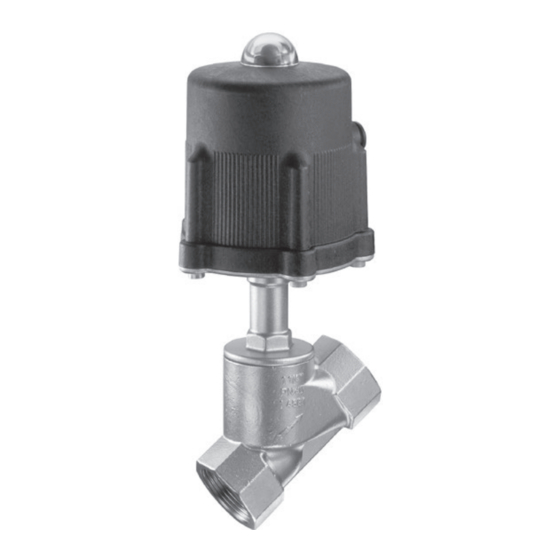
- Page 1 Type 3353 Angle Seat Valve Mounting and Operating Instructions EB 8139 EN Edition August 2017...
- Page 2 Î For the safe and proper use of these instructions, read them carefully and keep them for later reference. Î If you have any questions about these instructions, contact SAMSON‘s After-sales Service Department (aftersalesservice@samson.de). The mounting and operating instructions for the devices are included in the scope of delivery.
-
Page 3: Table Of Contents
Contents Safety instructions and measures ..............5 Notes on possible severe personal injury ............7 Notes on possible personal injury ..............7 Notes on possible property damage ..............8 Markings on the control valve ................9 Valve nameplate ....................9 Design and principle of operation ..............10 Fail-safe action ....................10 Technical data .....................12 Dimensions and weights ................13... - Page 4 Contents Ordering spare parts and operating supplies ..........28 Malfunctions ....................29 Troubleshooting ...................29 Emergency action ..................30 Decommissioning and disassembly ..............31 Decommissioning ..................31 Removing the valve from the pipeline .............31 Disposal ......................31 Annex......................32 10.1 After-sales service ..................32 10.2 Certificates ....................32 10.3 Spare parts ....................34 EB 8139 EN...
-
Page 5: Safety Instructions And Measures
1 Safety instructions and measures Intended use The Type 3353 Angle Seat Valve is designed for on/off service in process engineering and plants with industrial requirements. The valve is suitable for liquids, vapors and gases at tem- peratures from –10 to +180 °C and a pressure rating of PN 40. The angle seat valve is com- bined with a pneumatic piston actuator. - Page 6 Î Check with the plant operator for details on further protective equipment. Revisions and other modifications Revisions, conversions or other modifications to the product are not authorized by SAMSON. They are performed at the user's own risk and may lead to safety hazards, for example. Fur- thermore, the product may no longer meet the requirements for its intended use.
-
Page 7: Notes On Possible Severe Personal Injury
Safety instructions and measures Referenced documentation The mounting and operating instructions of the mounted valve accessories (e.g. u EB 8357 for Type 4740 Limit Switch) apply in addition to these mounting and operating instructions. 1.1 Notes on possible severe personal injury DANGER Risk of bursting in pressure equipment. Valves and pipelines are pressure equipment. -
Page 8: Notes On Possible Property Damage
Safety instructions and measures WARNING Risk of burn injuries due to hot or cold components and pipelines. Depending on the process medium, valve components and pipelines may get very hot or cold and cause burn injuries. Î Allow components and pipelines to cool down or heat up. Î... -
Page 9: Markings On The Control Valve
Markings on the control valve 2 Markings on the control valve 2.1 Valve nameplate SAMSON 3353 Actuator area and number of actuator springs (I or II) Max. Diff.druck/pressure ∆p in bar Required signal pressure in bar Stelldruck Antrieb Supply Act. size... -
Page 10: Design And Principle Of Operation
Design and principle of operation 3 Design and principle of oper- 3.1 Fail-safe action ation The fail-safe position of the valve upon sup- ply air (signal pressure) failure is determined The pneumatic control valve consists of an by how the piston and actuator spring are angle seat valve with a soft-seated plug and arranged in the pneumatic actuator. - Page 11 Design and principle of operation Fail-close (FA) Fail-open (FE) FA/NC/TS FE/NO/TR Body Radial shaft seal Piston Vent plug Plug (with plug/actuator stem) Filter Spring Signal pressure connection V-ring packing Fig. 2: Type 3353 Angle Seat Valve EB 8139 EN...
-
Page 12: Technical Data
Design and principle of operation 3.2 Technical data The nameplate provides information on the control valve version (see section 2.1). More in- formation is available in Data Sheet u T 8139. Table 1: Technical data Valve sizes DN 15 to 50 · NPS ½ to 2 Material 1.4408 Type of connection... -
Page 13: Dimensions And Weights
Design and principle of operation 3.3 Dimensions and weights Valve size DN (NPS) 15 (½) 20 (¾) 25 (1) 32 (1¼) 40 (1½) 50 (2) FTF dimension L End-to-end length L1 Height inc. actuator H Body connection G ½ G ¾ G 1¼ G 1½... -
Page 14: Permissible Differential Pressures
Design and principle of operation 3.4 Permissible differential pressures The specifications for the standard version have a dark gray background. 3.4.1 Version FA/NC with fail-safe position: fail-close 15 · 20 25 · 32 40 · 50 Pressure rating ½ · ¾ 1 ·... - Page 15 Design and principle of operation Control valve DN 25 · DN 32 25 · 32 Control valve DN 25 (NPS 1) · DN 32 (NPS 1¼) Pressure rating 1 · 1¼ [bar] ∆ Actuator Signal ∆p 60 cm²/Ø90 pressure 5 bar 6 bar 30 cm² Ø = 63 mm 7 bar 30 cm²/ Ø63 8 bar...
-
Page 16: Measures For Preparation
− Observe storage instructions. Note − Avoid long storage times. Do not remove the packaging until immedi- Contact SAMSON in case of different stor- ately before installing the valve into the pipe- age conditions or long storage periods. line. Proceed as follows to lift and install the con-... -
Page 17: Preparation For Installation
Measures for preparation − Make sure that the ambient air is free of acids or other corrosive media. − Observe the permissible ambient tem- peratures (see section 3.2). − Do not place any objects on the control valve. 4.4 Preparation for installation Î... -
Page 18: Mounting And Start-Up
Mounting and start-up 5 Mounting and start-up 4. Install the valve free of stress and with the least amount of vibrations as possible. The pneumatic control valve is delivered 5. Depending on the field of application, ready for use. allow the valve to cool down or heat up to reach ambient temperature before 5.1 Installing the valve into the start up. -
Page 19: Additional Fittings
Strainers 1440 N 3.8 bar 60 cm² FA/NC/TS We recommend installing a SAMSON 2160 N 5.4 bar strainer upstream of the valve. It prevents sol- id particles in the process medium from damaging the valve. Additional actuator spring (changing the spring force) Fail-close (FA/NC/TS) valves with the valve sizes DN 40 and 50 (NPS 1½... -
Page 20: Quick Check
− Observe the maximum permissible pres- sure for valve and plant. Note The plant operator is responsible for per- forming the pressure test. SAMSON's Af- ter-sales Service department can support you to plan and perform a pressure test for your plant. -
Page 21: Operation
Operation 6 Operation Immediately after completing mounting and start-up (see section 5), the valve is ready for use. WARNING Risk of personal injury when the actuator vents. Wear eye protection when working in close proximity to the control valve. WARNING Risk of burn injuries due to hot or cold com- ponents and pipelines. -
Page 22: Servicing
− If possible, drain the process medium from all the plant sections concerned and the Note valve. The control valve was checked by SAMSON − Wear protective clothing, safety gloves, before it left the factory. and eyewear. − Certain test results (seat leakage and leak... -
Page 23: Replacing The Gaskets
(1). − Only use original spare parts by SAMSON, which comply with the original 2. Remove the body gasket (31). Carefully specifications. clean the sealing faces in the valve body (1) and seat bore. -
Page 24: Replacing The Packing
Servicing 4. Remove the plug disk (42) and PTFE seal 4. Lift off the spring (20). (28). Thoroughly clean the plug disk. 5. Unscrew the nut (49) from the plug/actu- 5. Insert a new PTFE seal (28). ator stem using a socket wrench, while holding the plug/actuator stem (14) sta- 6. - Page 25 Servicing Fail-open (FE) Fail-close (FA) Fig. 5: Replacing the packing EB 8139 EN...
- Page 26 Servicing the packing chamber thoroughly. Renew 22. Insert the washer (46) and spring (20) the packing. into the piston (3). 13. Slide the plug/actuator stem (14) into the 23. Tighten the nut (49) intended for fasten- valve bonnet (10). ing the piston, while holding the plug/ actuator stem (14) stationary at the flat- 14.
- Page 27 Servicing 8. Unscrew the threaded bushing (11) to- Tighten the threaded bushing only to the gether with the actuator base (6) from point where the actuator base (6) can the valve bonnet (10) using an 24 mm still rotate on the slip washers (38). open-end wrench.
-
Page 28: Tightening Torques
7.5 Ordering spare parts and operating supplies Table 2: Tightening torques Contact your nearest SAMSON subsidiary for the valve bonnet (10) or the SAMSON After-sales Service depart- Valve size Tightening ment for information on spare parts, lubri- torque cants and tools. -
Page 29: Malfunctions
Depending on the operating conditions, check the valve at certain intervals to prevent possi- ble failure before it can occur. Operators are responsible for drawing up an inspection plan. SAMSON's After-sales Service department can support you to draw up an inspection plan for your plant. -
Page 30: Emergency Action
2. Check the valve for damage. If neces- sary, contact SAMSON's After-sales Ser- vice department. Putting the valve back into operation after a malfunction Î Slowly open the shut-off valves. Allow the process medium to slowly flow into the valve. -
Page 31: Decommissioning And Disassembly
Decommissioning and disassembly 9 Decommissioning and 9.1 Decommissioning disassembly 1. Close the shut-off valve in the pipeline. 2. Completely drain the pipelines and DANGER valve. Risk of bursting in pressure equipment. 3. Depressurize the plant. Valves and pipelines are pressure equip- 4. -
Page 32: Annex
After-sales Service You can reach the After-sales Service De- partment at aftersalesservice@samson.de. Addresses of SAMSON AG and its subsid- iaries The addresses of SAMSON AG, its subsidiaries, representatives and service facilities worldwide can be found on the SAMSON website (u www.samson.de) or in... - Page 33 Modul A/Module A SAMSON erklärt in alleiniger Verantwortung für folgende Produkte:/For the following products, SAMSON hereby declares under its sole responsibility: Geräte/Devices Bauart/Series Typ/Type Ausführung/Version DIN, Gehäuse GG, DN 65-125, Gehäuse GGG, DN 50-80, Fluide G2, L1, L2 Durchgangsventil/Globe valve...
-
Page 34: Spare Parts
Annex 10.3 Spare parts Body Spring washer Actuator housing Cap screw Piston Hexagon nut Dome Countersunk screw Actuator base Vent plug Valve bonnet Retaining screw (threaded pin) Threaded bushing Filter Plug (with plug/actuator stem) Spring Compression spring V-ring packing Piston ring Radial shaft seal PTFE seal Body gasket (seal) - Page 35 EB 8139 EN...
- Page 36 SAMSON AG · MESS- UND REGELTECHNIK Weismüllerstraße 3 · 60314 Frankfurt am Main, Germany Phone: +49 69 4009-0 · Fax: +49 69 4009-1507 EB 8139 EN samson@samson.de · www.samson.de...
Need help?
Do you have a question about the 3353 and is the answer not in the manual?
Questions and answers