
Related Manuals for Ruhrpumpen SPN


Summary of Contents for Ruhrpumpen SPN
- Page 1 DOCUMENT COVER SHEET Customer Name Project No MAKON INC 121000428 Customer PO No. Ruhrpumpen DCN 18-18 121000428-006 Pump Tag No. Document Rev P-6201 Pump Manual Revision History Date 19-Jul-19...
- Page 2 Installation, Operation and Maintenance Manual...
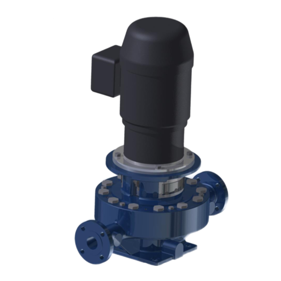
- Page 3 These units are vertical process pumps of the overhung, closed couple configuration and identified by Ruhrpumpen as SPN. It is recommended that the services of a Ruhrpumpen installation technician be employed for the installation and initial starting of the pump. Such service will help to ensure the user that the equipment is properly installed, and will provide an excellent opportunity for the plant operator to receive useful tips and guidelines relative to the unit.
- Page 4 Single Stage, Overhung, Closed Couple OH5 Pump Information in this manual is believed to be reliable, but it is not guaranteed by Ruhrpumpen as to its completeness or accuracy. © 2018 Ruhrpumpen All Rights Reserved. V1.100518...
-
Page 5: Table Of Contents
Single Stage, Overhung, Closed Couple OH5 Pump CONTENTS 1. PRODUCT DESCRIPTION ........................6 1.1 INTRODUCTION ..........................6 1.2 PUMP CASE, IMPELLER, AND WEAR RINGS ..................7 1.2.1 Pump Case ..........................7 1.2.2 Impeller ............................ 7 1.2.3 Seal Chamber ..........................7 SAFETY.............................. - Page 6 7.5 SHORT-TERM SHUTDOWN ......................33 7.6 LONG-TERM SHUTDOWN......................34 8. MAINTENANCE ............................ 35 8.1 DISASSEMBLY ..........................35 8.1.1 SPN Pump Disassembly ......................36 8.2 INSPECTION AND CLEANING ......................37 8.3 REASSEMBLY ..........................38 8.3.1 SPN Pump Reassembly ......................38 9. SPARE PARTS ............................
-
Page 7: Product Description
1.1 INTRODUCTION Ruhrpumpen pumps of type SPN are vertically in-line, mounted over their own base, centrifugal, closed couple pumps, with a vertically (radially) split case, centerline supported heavy-duty construction with an overhung impeller and are catalogued as OH5 pumps. These pumps are... -
Page 8: Pump Case, Impeller, And Wear Rings
Single Stage, Overhung, Closed Couple OH5 Pump The SPN is a single stage, single suction pump. For these pumps, rotation is clockwise as viewed from the driver (coupling) end. The following information is included in the nameplate of your pump unit: •... -
Page 9: Safety
The responsibilities and supervision of the personnel must be exactly defined by the plant operator. If the staff does not have the necessary knowledge, they must be trained and instructed. Training may be performed by a Ruhrpumpen representative on behalf of the plant operator. V1.100518... -
Page 10: Hazards In The Event Of Non-Compliance With The Safety Instructions
Single Stage, Overhung, Closed Couple OH5 Pump Moreover, the plant operator is to make sure that the contents of the operating manual are fully understood by the personnel. 2.3 HAZARDS IN THE EVENT OF NON-COMPLIANCE WITH THE SAFETY INSTRUCTIONS Non-compliance with the safety instructions may produce a risk to the personnel as well as to the environment and the unit and results in loss of any right to claim damages. -
Page 11: Safety Instructions Relevant For Maintenance, Inspection And Assembly Work
Modifications may be made to the machine only after consultation with a Ruhrpumpen representative. Using spare parts and accessories authorized by Ruhrpumpen is in the interest of safety. The use of parts not authorized by the dealer exempt the manufacturer from any liability, voiding the warranty. -
Page 12: Transport & Storage
Remove unit only by properly supporting the wooden shipping skid. After unloading, inspect the pump, check the shipment against the packing list, and report damages or shortages immediately to freight carrier and to the designated Ruhrpumpen representative. Do not place lifting rig around the suction and discharge flanges or under the baseplate. -
Page 13: Storing
Single Stage, Overhung, Closed Couple OH5 Pump When transporting with a crane, the rope should be slung round the unit as shown in the figure below. The rope should not be slung around the lugs attached to the motor or around the lugs attached to the pump. - Page 14 Return the unit to the shipping crate. When the pump is to be installed, remove all the protective coatings and desiccant and drain all oils. One month before installation, a Ruhrpumpen representative should be employed to conduct a final inspection. V1.100518...
- Page 15 Single Stage, Overhung, Closed Couple OH5 Pump To properly store the pump for periods longer than one month, follow these steps: Store the pump in a clean, dry area, or cover it with a loose tarp (the tarp must be loose in order to prevent condensation).
-
Page 16: Conservation
Single Stage, Overhung, Closed Couple OH5 Pump Be careful not to overheat, since keeping the temperature of the motor frame 9 °F (5 °C) above the surrounding ambient temperature is sufficient. After the storing period, follow the next steps as start-up preparations: Motor should be thoroughly inspected and cleaned to restore to an “As Shipped”... -
Page 17: Installation
NOTE: The information in this section is intended as a general guideline. For further information refer to the corresponding section in API Recommended Practices 686. IMPORTANT: The design of foundations is not the responsibility of Ruhrpumpen. It is therefore recommended that the customer consult a competent specialist skilled in the field of foundations, to insure proper design/installation of the foundation. -
Page 18: Leveling Baseplate
Single Stage, Overhung, Closed Couple OH5 Pump It is recommended to build the foundation approximately 3 inches (76 mm) larger overall than the pump baseplate to provide ample anchorage for the foundation bolts. 3.1. Since water can accidentally flow in the floor, a height for the surface of the foundation of 4 inches (100 mm) at least above floor level is recommended. - Page 19 Single Stage, Overhung, Closed Couple OH5 Pump To continue with the leveling procedure: Remove the pump and driver from the base to facilitate the leveling procedure. This will facilitate the next steps and prevent distortion of the baseplate. If alignment is to be performed with wedges, place steel blocks and wedges (or shim packs) as closely as possible to the foundation bolts.
-
Page 20: Grouting
Single Stage, Overhung, Closed Couple OH5 Pump Figure 4.1 Baseplate leveling planes The alignment of the baseplate is effected with the help of adjusting screws, or wedges, depending on the preparation of the baseplate. NOTE: When using jacking bolts, each one should have a mounting pad, to distribute the stresses evenly. -
Page 21: Grouting Precautions
Single Stage, Overhung, Closed Couple OH5 Pump • Risers or funnels for guiding grout. • Sufficient oil paint for grout protective covering. 4.3.2 Grouting Precautions During all the grouting process, the involved personnel must follow these safety precautions: Wear goggles or face shields, aprons, and protective gloves at all times. Wear dust masks if in contact with the dry aggregates. - Page 22 Fill the holes with grout. Tighten the foundation bolts with an appropriate torque value. In case of doubt, please contact your Ruhrpumpen representative. Apply oil paint to exposed grout to protect from air and moisture. Use a lifting rig to position the pump and driver on their baseplate so that the mounting feet line up with their respective tapped holes.
-
Page 23: Leveling Foundation Plate
Single Stage, Overhung, Closed Couple OH5 Pump NOTE: *If by client specification the pump is to be used in a service where grouting will not be possible, for example fire duty, it is responsibility of the customer to use a PIP baseplate. Otherwise, please note that baseplates are not pre-grouted, therefore this grouting procedure shall be followed by the customer. - Page 24 Single Stage, Overhung, Closed Couple OH5 Pump Figure 4.2 Foundation bolting for leveling (the image is not scaled, for illustrative purpose only). The deviation from the horizontal plane should not exceed +/- 0.3 mm per meter. After aligning the bolts, they have to be grounded with grout without cavities. When the grout has hardened, the required height and flange alignment are checked and adjusted.
-
Page 25: Piping And Alignment
Single Stage, Overhung, Closed Couple OH5 Pump 5. PIPING AND ALIGNMENT These units are furnished for a specific service condition. Any change in the hydraulic system may affect the pump performance adversely. The connection of the piping must be carried out with utmost care; otherwise, the pumping medium can escape during operation, which can seriously endanger the operating personnel. -
Page 26: Piping The System
API Recommended Practices 686. IMPORTANT: The design of piping and related systems is not the responsibility of Ruhrpumpen. It is, therefore, recommended that the customer consult a competent specialist skilled in the field of piping to insure proper design/installation of all the piping. - Page 27 Single Stage, Overhung, Closed Couple OH5 Pump Figure 5.1. Correct mounting of a cone type strainer. Disconnect the piping from the pump if you heat one side of the pipe to align the pipe to the pump. Pump and pipe flanges must be parallel; they should mate together without effort, and with the bolt holes properly in line.
- Page 28 Single Stage, Overhung, Closed Couple OH5 Pump No obstruction within at least five pipe diameters of the suction flange should be fitted. Do not install unsupported piping on the pump. Make sure electrical connections do not impose any stress on the pump unit. ...
-
Page 29: Lubrication
Single Stage, Overhung, Closed Couple OH5 Pump 6. LUBRICATION 6.1 DRIVER LUBRICATION For proper lubrication of the driver bearings, refer to the appropriate section on the driver manufacturer’s manual. 6.2 MECHANICAL SEAL LUBRICATION For the proper lubrication of the mechanical seal, refer to the provided seal plan drawing and the appropriate section of the mechanical seal manufacturer’s manual. -
Page 30: Operation
Single Stage, Overhung, Closed Couple OH5 Pump 7. OPERATION 7.1 PRIMING Before starting any centrifugal pump it is necessary that the pump casing and the suction pipe are completely filled with liquid. Priming can be done in the following ways: •... -
Page 31: Startup
Single Stage, Overhung, Closed Couple OH5 Pump 7.2 STARTUP Every time before the pump is started up the safety devices must be mounted and fastened. In order to avoid risks of injury or damage, all pump units must be equipped with emergency-stop devices. -
Page 32: Operating Check
To monitor flow, pressure, temperature, and lubrication, regular visual inspection and monitoring is advisable and/or necessary during operation. Ruhrpumpen recommends checking the pump constantly at regular intervals in order to detect problems early, in case they arise. The operational check routine must include at least the following points:... - Page 33 Single Stage, Overhung, Closed Couple OH5 Pump Beware of freely rotating parts, when the pump is in operation there is a high risk of injury. • Check at regular intervals that the safety equipment is sound and is arranged and fastened according to the regulations, and energized where applicable.
-
Page 34: Stopping
Single Stage, Overhung, Closed Couple OH5 Pump 7.4 STOPPING Throttle pump discharge to minimum flow. WARNING: do not close suction valve, this will cause the pump to run dry. Turn the power off to the driver. Close the pump discharge valve. Observe the run-down of the pump until full stop. -
Page 35: Long-Term Shutdown
Single Stage, Overhung, Closed Couple OH5 Pump If the pump comes to a sudden halt, or if the pump was switched off because of a possible danger, it must be checked for damage. 7.6 LONG-TERM SHUTDOWN Follow the stopping procedure described in SECTION 7.4 - STOPPING. Disconnect the vent filter and seal openings on the bearing housing to lessen the exchange of air. -
Page 36: Maintenance
Single Stage, Overhung, Closed Couple OH5 Pump 8. MAINTENANCE To perform the maintenance of the SPN pump, no special (custom made) tools are needed. Before initiating maintenance procedures disconnect all power sources to the equipment and discharge any parts which may retain an electric charge. Use proper locks to avoid accidental start-up of the pump system. -
Page 37: Spn Pump Disassembly
Special precautions must be observed when handling mechanical seals so as not to damage the lapped faces of the seal. 8.1.1 SPN Pump Disassembly Stop the pump. See SECTION 7.4 - STOPPING. Drain all possible fluids from the pump case. -
Page 38: Inspection And Cleaning
Untighten and remove the motor bolts that secure the motor stool to the motor. Remove the motor stool from the motor. The SPN pump disassembly process has been completed. 8.2 INSPECTION AND CLEANING Thoroughly clean all parts and dry with compressed air or a clean, lint free cloth. -
Page 39: Reassembly
Single Stage, Overhung, Closed Couple OH5 Pump 8.3 REASSEMBLY 8.3.1 SPN Pump Reassembly Place the motor on a flat surface. Figure 8.1 Placing the motor on a flat surface. Make sure the motor is safely held in place on the surface. - Page 40 Single Stage, Overhung, Closed Couple OH5 Pump Insert the motor stool over the motor shaft until it reaches the motor. Figure 8.2 Inserting the motor stool over the motor shaft until it reaches the motor. Place and tighten the motor bolts to secure the motor stool to the motor. Figure 8.3 Placing and tightening the motor bolts to secure the motor stool to the motor.
- Page 41 Single Stage, Overhung, Closed Couple OH5 Pump Insert the mechanical seal gland studs on the mechanical seal gland. Figure 8.4 Inserting the mechanical seal gland studs on the mechanical seal gland. The mechanical seal gland studs are inserted on the mechanical seal gland for assembly purposes.
- Page 42 Single Stage, Overhung, Closed Couple OH5 Pump Insert the mechanical seal over the shaft until it reaches the mechanical seal gland. Figure 8.6 Inserting the mechanical seal over the shaft until it reaches the mechanical seal gland. Insert the shaft sleeve over the shaft. Figure 8.7 Inserting the shaft sleeve over the shaft.
- Page 43 Single Stage, Overhung, Closed Couple OH5 Pump Insert the shaft sleeve pin in one of the holes of the shaft sleeve. Figure 8.8 Inserting the shaft sleeve pin in one of the holes of the shaft sleeve. Insert the throat bushing inside the case cover. Figure 8.9 Inserting the throat bushing inside the case cover.
- Page 44 Single Stage, Overhung, Closed Couple OH5 Pump Insert the case cover over the shaft until it reaches the motor stool. Figure 8.10 Inserting the case cover over the shaft until it reaches the motor stool. Place and tighten the hex bolts to secure the case cover to the motor stool. Figure 8.11 Placing and tightening the hex bolts to secure the case cover to the motor stool.
- Page 45 Single Stage, Overhung, Closed Couple OH5 Pump Adjust the mechanical seal gland studs. Figure 8.12 Adjusting the mechanical seal gland studs. Place and tighten the mechanical seal gland hex nuts to secure the mechanical seal gland to the case cover. Figure 8.13 Placing and tightening the mechanical seal gland hex nuts to secure the mechanical seal gland to the case cover.
- Page 46 Single Stage, Overhung, Closed Couple OH5 Pump Insert the back case wear ring inside the casing cover. Figure 8.14 Inserting the back case wear ring inside the casing cover. Insert the back impeller wear ring on the impeller. Figure 8.15 Inserting the back impeller wear ring on the impeller. V1.100518...
- Page 47 Single Stage, Overhung, Closed Couple OH5 Pump Insert the front impeller wear ring on the impeller. Figure 8.16 Inserting the front impeller wear ring on the impeller. Insert the impeller over the shaft until it reaches the shaft sleeve. Figure 8.17 Inserting the impeller over the shaft until it reaches the shaft sleeve. ...
- Page 48 Single Stage, Overhung, Closed Couple OH5 Pump Insert the impeller key on the impeller and shaft keyways. Figure 8.18 Inserting the impeller key on the impeller and shaft keyways. Place and tighten the impeller nut on the shaft. Figure 8.19 Placing and tightening the impeller nut on the shaft. V1.100518...
- Page 49 Single Stage, Overhung, Closed Couple OH5 Pump Place and tighten the socket set screws on the impeller nut. Figure 8.20 Placing and tightening the socket set screws on the impeller nut. Place the case on a flat surface. Figure 8.21 Placing the case on a flat surface. V1.100518...
- Page 50 Single Stage, Overhung, Closed Couple OH5 Pump Insert the front case wear ring inside the case. Figure 8.22 Inserting the front case wear ring inside the case. Insert the case gasket on the case. Figure 8.23 Inserting the case gasket on the case. V1.100518...
- Page 51 Single Stage, Overhung, Closed Couple OH5 Pump Insert the rotor assembly inside the case. Figure 8.24 Inserting the rotor assembly inside the case. Place and tighten the hex bolts to secure the rotor assembly to the case. Figure 8.25 Placing and tightening the hex bolts to secure the rotor assembly to the case. V1.100518...
- Page 52 Single Stage, Overhung, Closed Couple OH5 Pump Place and secure the mechanical seal guards on the motor stool. Figure 8.26 Placing and securing the mechanical seal guards on the motor stool. The SPN pump assembly process has been completed. Figure 8.27 SPN complete pump. V1.100518...
-
Page 53: Spare Parts
The quantities of spare parts given on the list below are the minimum standard quantities to be had. However, these quantities may vary depending on individual working conditions. For more information, please contact a Ruhrpumpen representative. DESCRIPTION STARTUP 1 - 3 YEARS... -
Page 54: Parts Information
Single Stage, Overhung, Closed Couple OH5 Pump 10. PARTS INFORMATION Figure 10.1 Sectional Drawing SPN Pump. V1.100518... - Page 55 Single Stage, Overhung, Closed Couple OH5 Pump Parts List SPN Pump. ITEM DESCRIPTION ITEM DESCRIPTION CASE 503.2 BACK IMPELLER WEAR RING CASE COVER SHAFT SLEEVE IMPELLER SHAFT SLEEVE PIN MOTOR STOOL MOTOR JOINT RING 901.1 HEXAGONAL BOLT - CASE COVER MECHANICAL SEAL 901.2...
-
Page 56: Troubleshooting Chart
SHAFT SEAL properly aligned. a. Inner pump parts a. Change worn parts. are worn. b. Consult a Ruhrpumpen dealer. b. Density or viscosity c. Apply correct voltage to the motor. of pumped fluid is d. Check the cables, connections and fuses. - Page 57 Install vent valve or lay piping elsewhere. h. Feed pipe or j. Change worn parts. impeller plugged. k. Consult a Ruhrpumpen dealer. CAPACITY OR i. Formation of air l. Apply correct voltage to the motor. DISCHARGE pockets in the m.
- Page 58 Single Stage, Overhung, Closed Couple OH5 Pump RUHRPUMPEN PLANTS USA, Tulsa & Orland MEXICO, Monterrey BRAZIL, Río De Janeiro ARGENTINA, Buenos Aires GERMANY, Witten EGYPT, Suez INDIA, Chennai CHINA, Changzhou UK, Lancing V1.100518 V1.100518...
Need help?
Do you have a question about the SPN and is the answer not in the manual?
Questions and answers