Table of Contents
Advertisement
Quick Links
www.ti.com
EVM User's Guide: LM644A2QEVM-S2100T
LM644A2QEVM-S2100T 36V, 12A, Single-Output, Dual-
Phase, Synchronous Buck Converter Evaluation Board
Description
The LM644A2QEVM-S2100T evaluation board
showcases the features and performance of
the LM644A2-Q1, dual buck DC/DC converter
with integrated power MOSFETs. The EVM
provides a single 12A output with dual-phase
interleaved configuration. The output voltages can be
programmed to a fixed 3.3V, 5V or adjustable using
external feedback resistors.
Features
•
12A output dual-phase interleaved synchronous
buck converter
•
Wide operating range of up to 36V
•
Default output voltage: 3.3V
•
Default switching frequency: 2.1MHz
•
High efficiency across a wide load-current range
•
Input EMI filter with electrolytic capacitor for
parallel damping (input filter can handle up to 8A
input current)
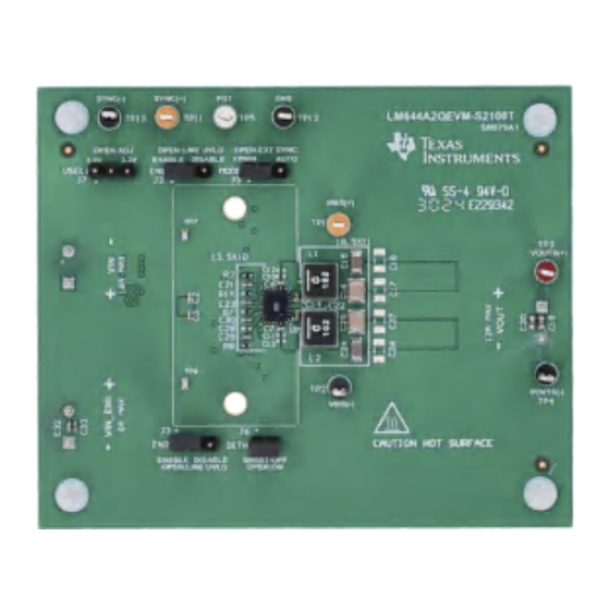
LM644A2QEVM-S2100T (Top View)
SLVUCX4 – OCTOBER 2024
Submit Document Feedback
•
Clock synchronization and FPWM mode provide
constant switching frequency across the full load
range
•
Integrated input capacitors enable low-noise
switching performance
•
Pin selectable spread spectrum
•
Peak current-mode control architecture with
external loop compensation.
•
Peak current limiting with hiccup-mode overcurrent
protection
•
Thermal shutdown protection with hysteresis
•
PGOOD indicator
•
Programmable input UVLO
•
6-layer, 2-oz PC board design with mountable
converter heat sink (heat sink provided)
Applications
•
Automotive infotainment and
media
•
Automotive ADAS
•
General-purpose dual buck converters
LM644A2QEVM-S2100T 36V, 12A, Single-Output, Dual-Phase, Synchronous
Copyright © 2024 Texas Instruments Incorporated
hub,
USB
charging,
information display
and
body electronics
LM644A2QEVM-S2100T (Bottom View)
Buck Converter Evaluation Board
Description
cluster:
head
unit,
1
Advertisement
Table of Contents

Related Manuals for Texas Instruments LM644A2QEVM-S2100T


Summary of Contents for Texas Instruments LM644A2QEVM-S2100T
- Page 1 Automotive ADAS body electronics input current) • General-purpose dual buck converters LM644A2QEVM-S2100T (Top View) LM644A2QEVM-S2100T (Bottom View) SLVUCX4 – OCTOBER 2024 LM644A2QEVM-S2100T 36V, 12A, Single-Output, Dual-Phase, Synchronous Submit Document Feedback Buck Converter Evaluation Board Copyright © 2024 Texas Instruments Incorporated...
-
Page 2: Kit Contents
The EVM operates when the input voltage is in the range of 3V to 6V, but enters a dropout mode if there is insufficient input voltage to regulate output voltages. LM644A2QEVM-S2100T 36V, 12A, Single-Output, Dual-Phase, Synchronous SLVUCX4 – OCTOBER 2024... -
Page 3: Device Information
Negative input power connection for EMI test. VOUT+ Positive output power connection. VOUT– Negative output power connection. SLVUCX4 – OCTOBER 2024 LM644A2QEVM-S2100T 36V, 12A, Single-Output, Dual-Phase, Synchronous Submit Document Feedback Buck Converter Evaluation Board Copyright © 2024 Texas Instruments Incorporated... - Page 4 Probe point for SS. The soft-start pin is also used for fault communication between the primary and the secondary device in 4- or 6-phase configuration. COMP Probe point for COMP. COMP is the output of error amplifier. LM644A2QEVM-S2100T 36V, 12A, Single-Output, Dual-Phase, Synchronous SLVUCX4 – OCTOBER 2024 Buck Converter Evaluation Board Submit Document Feedback...
-
Page 5: Test Equipment
(not going into thermal shutdown) of supporting a continuous load 1A higher than without. In this example, the thermal (convection) oven had an approximate airflow of 300-400 LFM. SLVUCX4 – OCTOBER 2024 LM644A2QEVM-S2100T 36V, 12A, Single-Output, Dual-Phase, Synchronous Submit Document Feedback Buck Converter Evaluation Board... - Page 6 = 12V 3.26 = 24V 3.25 Output Current [A] Figure 3-5. Load Regulation, VOUT = 3.3V, AUTO Mode LM644A2QEVM-S2100T 36V, 12A, Single-Output, Dual-Phase, Synchronous SLVUCX4 – OCTOBER 2024 Buck Converter Evaluation Board Submit Document Feedback Copyright © 2024 Texas Instruments Incorporated...
- Page 7 Figure 3-8. SYNC and Interleaving. No load Figure 3-9. Load Transient, 6A to 12A Figure 3-10. Bode Plot, VIN = 12V SLVUCX4 – OCTOBER 2024 LM644A2QEVM-S2100T 36V, 12A, Single-Output, Dual-Phase, Synchronous Submit Document Feedback Buck Converter Evaluation Board Copyright © 2024 Texas Instruments Incorporated...
- Page 8 3.1.3 EMI Performance VIN = 12V, VOUT = 3.3V, IOUT = 12A, spread spectrum enabled. Figure 3-11. CISPR 25 Conducted Emissions: 150kHz to 30MHz LM644A2QEVM-S2100T 36V, 12A, Single-Output, Dual-Phase, Synchronous SLVUCX4 – OCTOBER 2024 Buck Converter Evaluation Board Submit Document Feedback...
-
Page 9: Thermal Performance
Implementation Results 3.1.4 Thermal Performance Figure 3-12. 13.5VIN to 3.3VOUT, 8A CC load, 2.2MHz Operation Top Case Temperature SLVUCX4 – OCTOBER 2024 LM644A2QEVM-S2100T 36V, 12A, Single-Output, Dual-Phase, Synchronous Submit Document Feedback Buck Converter Evaluation Board Copyright © 2024 Texas Instruments Incorporated... - Page 10 4 Hardware Design Files 4.1 Schematic The EVM schematic is illustrated in Figure 4-1. Figure 4-1. EVM Schematic LM644A2QEVM-S2100T 36V, 12A, Single-Output, Dual-Phase, Synchronous Buck Converter Evaluation SLVUCX4 – OCTOBER 2024 Board Submit Document Feedback Copyright © 2024 Texas Instruments Incorporated...
- Page 11 Hardware Design Files Figure 4-2. EVM Schematic SLVUCX4 – OCTOBER 2024 LM644A2QEVM-S2100T 36V, 12A, Single-Output, Dual-Phase, Synchronous Buck Converter Evaluation Submit Document Feedback Board Copyright © 2024 Texas Instruments Incorporated...
-
Page 12: Pcb Layout
4.2 PCB Layout The PCB is 62-mils standard thickness with 2-oz copper on all layers. Figure 4-3. Top Component View Figure 4-4. Bottom Component View LM644A2QEVM-S2100T 36V, 12A, Single-Output, Dual-Phase, Synchronous SLVUCX4 – OCTOBER 2024 Buck Converter Evaluation Board Submit Document Feedback... - Page 13 Hardware Design Files Figure 4-5. Top Layer Copper Figure 4-6. Layer 2 Copper SLVUCX4 – OCTOBER 2024 LM644A2QEVM-S2100T 36V, 12A, Single-Output, Dual-Phase, Synchronous Submit Document Feedback Buck Converter Evaluation Board Copyright © 2024 Texas Instruments Incorporated...
- Page 14 Hardware Design Files www.ti.com Figure 4-7. Layer 3 Copper Figure 4-8. Layer 4 Copper LM644A2QEVM-S2100T 36V, 12A, Single-Output, Dual-Phase, Synchronous SLVUCX4 – OCTOBER 2024 Buck Converter Evaluation Board Submit Document Feedback Copyright © 2024 Texas Instruments Incorporated...
- Page 15 Hardware Design Files Figure 4-9. Layer 5 Copper Figure 4-10. Bottom Layer Copper (Viewed From Top) SLVUCX4 – OCTOBER 2024 LM644A2QEVM-S2100T 36V, 12A, Single-Output, Dual-Phase, Synchronous Submit Document Feedback Buck Converter Evaluation Board Copyright © 2024 Texas Instruments Incorporated...
- Page 16 J1, J4, J8 Terminal Block, 5mm, 2x1, Tin, TH 691 101 710 002 Wurth Elektronik 2x1, TH LM644A2QEVM-S2100T 36V, 12A, Single-Output, Dual-Phase, Synchronous Buck Converter Evaluation SLVUCX4 – OCTOBER 2024 Board Submit Document Feedback Copyright © 2024 Texas Instruments Incorporated...
- Page 17 Test Point, Multipurpose, Red, TH 5010 Keystone Electronics point White Multipurpose Test Test Point, Multipurpose, White, TH 5012 Keystone Electronics point SLVUCX4 – OCTOBER 2024 LM644A2QEVM-S2100T 36V, 12A, Single-Output, Dual-Phase, Synchronous Buck Converter Evaluation Submit Document Feedback Board Copyright © 2024 Texas Instruments Incorporated...
- Page 18 RES, 100 k, 1%, 0.1 W, 0603 RC0603FR-07100KL Yageo 0603 R4, R5 35.7k RES, 35.7 k, 1%, 0.1 W, 0603 RC0603FR-0735K7L Yageo 0603 LM644A2QEVM-S2100T 36V, 12A, Single-Output, Dual-Phase, Synchronous Buck Converter Evaluation SLVUCX4 – OCTOBER 2024 Board Submit Document Feedback Copyright © 2024 Texas Instruments Incorporated...
-
Page 19: Additional Information
2. Optimize the design for key parameters such as efficiency, footprint, and cost using the optimizer dial. 3. Compare the generated design with other possible designs from Texas Instruments. The WEBENCH Power Designer provides a customized schematic along with a list of materials with real-time pricing and component availability. - Page 20 STANDARD TERMS FOR EVALUATION MODULES Delivery: TI delivers TI evaluation boards, kits, or modules, including any accompanying demonstration software, components, and/or documentation which may be provided together or separately (collectively, an “EVM” or “EVMs”) to the User (“User”) in accordance with the terms set forth herein.
- Page 21 www.ti.com Regulatory Notices: 3.1 United States 3.1.1 Notice applicable to EVMs not FCC-Approved: FCC NOTICE: This kit is designed to allow product developers to evaluate electronic components, circuitry, or software associated with the kit to determine whether to incorporate such items in a finished product and software developers to write software applications for use with the end product.
- Page 22 www.ti.com Concernant les EVMs avec antennes détachables Conformément à la réglementation d'Industrie Canada, le présent émetteur radio peut fonctionner avec une antenne d'un type et d'un gain maximal (ou inférieur) approuvé pour l'émetteur par Industrie Canada. Dans le but de réduire les risques de brouillage radioélectrique à...
- Page 23 www.ti.com EVM Use Restrictions and Warnings: 4.1 EVMS ARE NOT FOR USE IN FUNCTIONAL SAFETY AND/OR SAFETY CRITICAL EVALUATIONS, INCLUDING BUT NOT LIMITED TO EVALUATIONS OF LIFE SUPPORT APPLICATIONS. 4.2 User must read and apply the user guide and other available documentation provided by TI regarding the EVM prior to handling or using the EVM, including without limitation any warning or restriction notices.
- Page 24 Notwithstanding the foregoing, any judgment may be enforced in any United States or foreign court, and TI may seek injunctive relief in any United States or foreign court. Mailing Address: Texas Instruments, Post Office Box 655303, Dallas, Texas 75265 Copyright © 2023, Texas Instruments Incorporated...
- Page 25 TI products. TI’s provision of these resources does not expand or otherwise alter TI’s applicable warranties or warranty disclaimers for TI products. TI objects to and rejects any additional or different terms you may have proposed. IMPORTANT NOTICE Mailing Address: Texas Instruments, Post Office Box 655303, Dallas, Texas 75265 Copyright © 2024, Texas Instruments Incorporated...
Need help?
Do you have a question about the LM644A2QEVM-S2100T and is the answer not in the manual?
Questions and answers