Table of Contents
Advertisement
Quick Links
www.ti.com
User's Guide
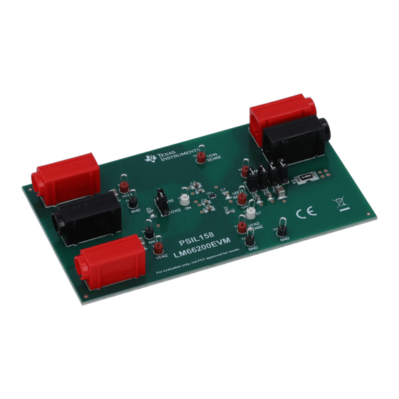
LM66200 Evaluation Module
This user's guide describes the characteristics, operation, and use of the LM66200 low I
Module (EVM). This document contains the complete EVM schematic diagram, printed-circuit board layouts, bill
of materials, and necessary intructions on how to properly operate the EVM.
1
Introduction.............................................................................................................................................................................2
1.1 Description.........................................................................................................................................................................
1.2 Features.............................................................................................................................................................................
Performance...........................................................................................................................................................2
3 LM66200EVM Configurations................................................................................................................................................
4
Schematic................................................................................................................................................................................4
Layout..............................................................................................................................................................................5
Setup................................................................................................................................................................................6
Equipment...........................................................................................................................................6
6.2 Setting up the LM66200EVM.............................................................................................................................................
7 Test Configuration..................................................................................................................................................................
(BOM)............................................................................................................................................................7
History.........................................................................................................................................................................9
Schematic..........................................................................................................................................4
Layer...................................................................................................................................................5
Figure 5-2. LM66200 Bottom Layer.............................................................................................................................................
Figure 7-1. LM66200 Setup With Test Equipment.......................................................................................................................
Table 1-1. LM66200 Modes of Operation....................................................................................................................................
Table 3-2. LM66200EVM Test Point Description.........................................................................................................................
Table 3-3. LM66200EVM Jumper Description.............................................................................................................................
Settings..............................................................................................................................................6
Table 8-1. LM66200EVM BOM....................................................................................................................................................
Trademarks
All trademarks are the property of their respective owners.
SLVUC50 - APRIL 2021
Submit Document Feedback
ABSTRACT
Table of Contents
List of Figures
List of Tables
Functionality...........................................................................................3
Copyright © 2021 Texas Instruments Incorporated
Table of Contents
ideal diode Evaluation
Q
2
2
3
6
6
5
6
2
3
3
7
LM66200 Evaluation Module
1
Advertisement
Table of Contents

Related Manuals for Texas Instruments LM66200EVM


Summary of Contents for Texas Instruments LM66200EVM
-
Page 1: Table Of Contents
Figure 5-2. LM66200 Bottom Layer............................. Figure 7-1. LM66200 Setup With Test Equipment........................List of Tables Table 1-1. LM66200 Modes of Operation............................ Table 3-1. LM66200EVM Input and Output Connector Functionality...................3 Table 3-2. LM66200EVM Test Point Description......................... Table 3-3. LM66200EVM Jumper Description.......................... -
Page 2: Introduction
1.1 Description The LM66200EVM is a two layer PCB that enables the evaluation of the LM66200 low IQ ideal diode. This EVM contains multiple jumpers to configure the different modes of operation of the LM66200. Table 1 lists the different modes of operation. -
Page 3: Lm66200Evm Configurations
Table 3 describes the different test points and functinality. Table 4 describes the jumper functionality and configurations. Table 3-1. LM66200EVM Input and Output Connector Functionality Input Connector and Test Point Label Description VIN1+... -
Page 4: Schematic
0.1uF 10.0k 10.0 10µF 100uF VIN2 VIN2 Sense LM66200DRLR VIN2 VIN2 1.6V to 5.5V 10µF 0.1uF 100uF TP10 TP11 TP12 Figure 4-1. LM66200EVM Schematic LM66200 Evaluation Module SLVUC50 – APRIL 2021 Submit Document Feedback Copyright © 2021 Texas Instruments Incorporated... -
Page 5: Pcb Layout
PCB Layout 5 PCB Layout Figure 2 Figure 3 show the LM66200EVM PCB layout images. Figure 5-1. LM66200 Top Layer Figure 5-2. LM66200 Bottom Layer SLVUC50 – APRIL 2021 LM66200 Evaluation Module Submit Document Feedback Copyright © 2021 Texas Instruments Incorporated... -
Page 6: Test Setup
Two adjustable power supplies, 0 V–6 V at 2.5-A maximum • Oscilloscope • A passive or active load 6.2 Setting up the LM66200EVM Make sure the LM66200EVM has the default jumper settings described in Table Table 6-1. Default Jumper Settings Jumper Description Position... -
Page 7: Bill Of Materials (Bom)
Closed Top 100mil Shunt SPC02SYAN SH-J4, SH-J5 Gold, Black Solutions TP1, TP2, TP3, TP4, Test Point, Multipurpose, Red Multipurpose 5010 Keystone TP5, TP6 Red, TH Testpoint SLVUC50 – APRIL 2021 LM66200 Evaluation Module Submit Document Feedback Copyright © 2021 Texas Instruments Incorporated... - Page 8 Bill of Materials (BOM) www.ti.com Table 8-1. LM66200EVM BOM (continued) Designator Quantity Value Description Package Reference Part Number Manufacturer Test Point, Multipurpose, White Multipurpose TP7, TP8 5012 Keystone White, TH Testpoint Test Point, Multipurpose, Black Multipurpose TP9, TP10, TP11, TP12...
-
Page 9: Revision History
Revision History NOTE: Page numbers for previous revisions may differ from page numbers in the current version. DATE REVISION NOTES April 2021 Initial Release SLVUC50 – APRIL 2021 LM66200 Evaluation Module Submit Document Feedback Copyright © 2021 Texas Instruments Incorporated... - Page 10 STANDARD TERMS FOR EVALUATION MODULES Delivery: TI delivers TI evaluation boards, kits, or modules, including any accompanying demonstration software, components, and/or documentation which may be provided together or separately (collectively, an “EVM” or “EVMs”) to the User (“User”) in accordance with the terms set forth herein.
- Page 11 www.ti.com Regulatory Notices: 3.1 United States 3.1.1 Notice applicable to EVMs not FCC-Approved: FCC NOTICE: This kit is designed to allow product developers to evaluate electronic components, circuitry, or software associated with the kit to determine whether to incorporate such items in a finished product and software developers to write software applications for use with the end product.
- Page 12 www.ti.com Concernant les EVMs avec antennes détachables Conformément à la réglementation d'Industrie Canada, le présent émetteur radio peut fonctionner avec une antenne d'un type et d'un gain maximal (ou inférieur) approuvé pour l'émetteur par Industrie Canada. Dans le but de réduire les risques de brouillage radioélectrique à...
- Page 13 www.ti.com EVM Use Restrictions and Warnings: 4.1 EVMS ARE NOT FOR USE IN FUNCTIONAL SAFETY AND/OR SAFETY CRITICAL EVALUATIONS, INCLUDING BUT NOT LIMITED TO EVALUATIONS OF LIFE SUPPORT APPLICATIONS. 4.2 User must read and apply the user guide and other available documentation provided by TI regarding the EVM prior to handling or using the EVM, including without limitation any warning or restriction notices.
- Page 14 Notwithstanding the foregoing, any judgment may be enforced in any United States or foreign court, and TI may seek injunctive relief in any United States or foreign court. Mailing Address: Texas Instruments, Post Office Box 655303, Dallas, Texas 75265 Copyright © 2019, Texas Instruments Incorporated...
- Page 15 TI products. TI’s provision of these resources does not expand or otherwise alter TI’s applicable warranties or warranty disclaimers for TI products.IMPORTANT NOTICE Mailing Address: Texas Instruments, Post Office Box 655303, Dallas, Texas 75265 Copyright © 2021, Texas Instruments Incorporated...
Need help?
Do you have a question about the LM66200EVM and is the answer not in the manual?
Questions and answers