
Related Manuals for Texas Instruments LM36923HEVM


Summary of Contents for Texas Instruments LM36923HEVM
- Page 1 Using the LM36923HEVM Evaluation Module User's Guide Literature Number: SNVU509 January 2016...
-
Page 2: Table Of Contents
PWM Pin Control ....................... ASEL Pin Control ....................History & Macro Tab ................. Individual register read/write access ......................Macro Example ..................Updating USB2ANY Firmware Table of Contents SNVU509 – January 2016 Submit Documentation Feedback Copyright © 2016, Texas Instruments Incorporated... - Page 3 Example macro message box ................... USB2ANY firmware unknown update ..................USB2ANY firmware update step 1 ..................USB2ANY firmware update step 2 .................. USB2ANY firmware update complete SNVU509 – January 2016 List of Figures Submit Documentation Feedback Copyright © 2016, Texas Instruments Incorporated...
- Page 4 List of Tables ..................Device and Package Configurations ......................Bill of Materials ......................Macro commands List of Tables SNVU509 – January 2016 Submit Documentation Feedback Copyright © 2016, Texas Instruments Incorporated...
-
Page 5: Introduction
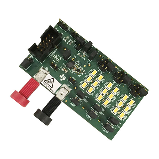
SNVU509 – January 2016 LM36923HEVM User's Guide Introduction The Texas Instruments LM36923HEVM evaluation module (EVM) helps designers evaluate the operation and performance of the LM36923H Highly Efficient Triple-String White LED driver. The device offers configurability via I C-compatible interface. The EVM contains six dual-LED and a single LED per string which can be easily configured to support 1, 2 or 3 parallel LED strings with 3, 4, 5, 6, 7, 8, 9, 10, 11, 12 or 13 series LEDs. -
Page 6: Setup
C slave address. A jumper is required to operate the EVM. The LM36923HEVM GUI provides a method for setting ASEL when a jumper is inserted between pins 2 and 4. When a jumper is inserted between pins 1 and 2 ASEL is connected to VIO through a 4.7-kΩ... -
Page 7: Setup
D307 is bypassed in the respective LED string. ILED1, ILED2, ILED3 -The LM36923HEVM provides a way to accurately measure the LED current through each LED string on board. Resistors RL1 , RL2 and RL3 (10 Ω) are placed between the cathode of last LED in each respective string and the LM36923H Current Sink Output. -
Page 8: Board Layout
Figure 9 Figure 10 show the board layout for the LM36923HEVM. The EVM offers resistors, capacitors, and jumpers to enable the device and to configure it as desired. The LM36923H will dissipate power, especially during high brightness maintained for a long duration. -
Page 9: Top Assembly Layer
Board Layout www.ti.com Figure 7. Top Assembly Layer Figure 8. Middle Layer 1 Routing SNVU509 – January 2016 LM36923HEVM User's Guide Submit Documentation Feedback Copyright © 2016, Texas Instruments Incorporated... -
Page 10: Middle Layer 2 Routing
Board Layout www.ti.com Figure 9. Middle Layer 2 Routing Figure 10. Bottom Assembly Layer (MIRRORED) LM36923HEVM User's Guide SNVU509 – January 2016 Submit Documentation Feedback Copyright © 2016, Texas Instruments Incorporated... -
Page 11: Schematic
Schematic www.ti.com Schematic Figure 11. LM36923EVM Schematic SNVU509 – January 2016 LM36923HEVM User's Guide Submit Documentation Feedback Copyright © 2016, Texas Instruments Incorporated... - Page 12 Highly Efficient Triple-String White LED Driver, Texas Instruments LM36923HYFFR YFF0012AHAH USB2ANY Header (shrouded), 100mil, 5x2, Gold, TH TE Connectivity 5103308-1 Standard Banana Jack, Insulated, Red Keystone 6091 LM36923HEVM User's Guide SNVU509 – January 2016 Submit Documentation Feedback Copyright © 2016, Texas Instruments Incorporated...
-
Page 13: Compatible Interface Program
USB2ANY interface box and interface software. The LM36923HEVM has the means to “plug into” the USB docking board. The USB docking board provides all the control signals for the simple interface. Power to the part must be provided externally. A USB cable (provided) must be connected to the board from a PC. -
Page 14: Lm36923H Software Reset
Selecting the "Reset" button sends the I C Software Reset command which sets all registers to their default values and updates all GUI fields. Figure 13. LM36923H Software Reset LM36923HEVM User's Guide SNVU509 – January 2016 Submit Documentation Feedback Copyright © 2016, Texas Instruments Incorporated... -
Page 15: Lm36923H Fault Flags
The contents of the LM36923H fault registers are read upon clicking the “Read” button. The registers are cleared upon read back. Figure 14. Fault Flags SNVU509 – January 2016 LM36923HEVM User's Guide Submit Documentation Feedback Copyright © 2016, Texas Instruments Incorporated... -
Page 16: Pwm Pin Control
PWM Pin Control The LM36923HEVM provides the user with the capability to control the PWM input without the need of an external source. The PWM signal will be low until the "PWM Enable" button is clicked or whenever the "Duty Cycle"... -
Page 17: Asel Pin Control
I C slave address used by the GUI is set to 0x37. If the LM36923HEVM ASEL jumper is set to a fixed setting the user will need to verify that the GUI Address Select setting matches the jumper on the EVM. -
Page 18: History & Macro Tab
History & Macro Tab The LM36923HEVM GUI provides history, register access and macro capability when the "History" checkbox is checked. The history information can be cleared by clicking the "Clear" button or saved to file by clicking the "Save to file ..." button. Clicking the "Save to file ..." button will open up a dialog box to select the file location and file name. -
Page 19: Individual Register Read/Write Access
LM36923H. Any read or write access is reflected in the history section in addition to the register box located to the right of the "Read" and "Write" buttons. Figure 18. Register read/write access SNVU509 – January 2016 LM36923HEVM User's Guide Submit Documentation Feedback Copyright © 2016, Texas Instruments Incorporated... -
Page 20: Macro Example
C-Compatible Interface Program www.ti.com Macro Example The LM36923HEVM GUI provides the user with the ability to create custom macros to configure the LM36923H with a single button click. Multiple macros can be created and saved in a single file as shown Figure Table 3. -
Page 21: Example Macro Loaded (Tool Tip Enabled)
Clicking the "Save All" button will save all defined macros into a single output file. Figure 20. Example macro loaded (tool tip enabled) SNVU509 – January 2016 LM36923HEVM User's Guide Submit Documentation Feedback Copyright © 2016, Texas Instruments Incorporated... -
Page 22: Example Macro Message Box
The message box opens when the "OK" keyword is executed in the Example macro. Macro execution is halted until the message box is closed by clicking the "OK" button. Figure 21. Example macro message box LM36923HEVM User's Guide SNVU509 – January 2016 Submit Documentation Feedback Copyright © 2016, Texas Instruments Incorporated... -
Page 23: Updating Usb2Any Firmware
Updating USB2ANY Firmware When the LM36923HEVM GUI is launched the USB2ANY firmware is checked to verify that it contains the correct version. If the USB2ANY firmware version does not match the user will be prompted to update the USB2ANY firmware. -
Page 24: Usb2Any Firmware Update Step
Figure 24. USB2ANY firmware update step 2 After the USB2ANY firmware is successfully updated the user must click the "Close" button to close the USB2ANY Firmware Loader and return control to the LM36923HEVM GUI. Figure 25. USB2ANY firmware update complete LM36923HEVM User's Guide SNVU509 –... - Page 25 STANDARD TERMS AND CONDITIONS FOR EVALUATION MODULES Delivery: TI delivers TI evaluation boards, kits, or modules, including any accompanying demonstration software, components, or documentation (collectively, an “EVM” or “EVMs”) to the User (“User”) in accordance with the terms and conditions set forth herein. Acceptance of the EVM is expressly subject to the following terms and conditions.
- Page 26 FCC Interference Statement for Class B EVM devices NOTE: This equipment has been tested and found to comply with the limits for a Class B digital device, pursuant to part 15 of the FCC Rules. These limits are designed to provide reasonable protection against harmful interference in a residential installation.
- Page 27 【無線電波を送信する製品の開発キットをお使いになる際の注意事項】 開発キットの中には技術基準適合証明を受けて いないものがあります。 技術適合証明を受けていないもののご使用に際しては、電波法遵守のため、以下のいずれかの 措置を取っていただく必要がありますのでご注意ください。 1. 電波法施行規則第6条第1項第1号に基づく平成18年3月28日総務省告示第173号で定められた電波暗室等の試験設備でご使用 いただく。 2. 実験局の免許を取得後ご使用いただく。 3. 技術基準適合証明を取得後ご使用いただく。 なお、本製品は、上記の「ご使用にあたっての注意」を譲渡先、移転先に通知しない限り、譲渡、移転できないものとします。 上記を遵守頂けない場合は、電波法の罰則が適用される可能性があることをご留意ください。 日本テキサス・イ ンスツルメンツ株式会社 東京都新宿区西新宿6丁目24番1号 西新宿三井ビル 3.3.3 Notice for EVMs for Power Line Communication: Please see http://www.tij.co.jp/lsds/ti_ja/general/eStore/notice_02.page 電力線搬送波通信についての開発キットをお使いになる際の注意事項については、次のところをご覧くださ い。http://www.tij.co.jp/lsds/ti_ja/general/eStore/notice_02.page SPACER EVM Use Restrictions and Warnings: 4.1 EVMS ARE NOT FOR USE IN FUNCTIONAL SAFETY AND/OR SAFETY CRITICAL EVALUATIONS, INCLUDING BUT NOT LIMITED TO EVALUATIONS OF LIFE SUPPORT APPLICATIONS.
- Page 28 Notwithstanding the foregoing, any judgment may be enforced in any United States or foreign court, and TI may seek injunctive relief in any United States or foreign court. Mailing Address: Texas Instruments, Post Office Box 655303, Dallas, Texas 75265 Copyright © 2015, Texas Instruments Incorporated...
- Page 29 IMPORTANT NOTICE Texas Instruments Incorporated and its subsidiaries (TI) reserve the right to make corrections, enhancements, improvements and other changes to its semiconductor products and services per JESD46, latest issue, and to discontinue any product or service per JESD48, latest issue.
Need help?
Do you have a question about the LM36923HEVM and is the answer not in the manual?
Questions and answers