Table of Contents
Advertisement
Quick Links
Advertisement
Table of Contents

Related Manuals for Advantech AIMB-Z20


Summary of Contents for Advantech AIMB-Z20
- Page 1 AIMB-Z20 中国自主化处理器 兆芯KX-6000系列平台 Mini-ITX主板...
- Page 2 Copyright /版权声明 The documentation and the software included with this product are copyrighted 2019 by Advantech Co., Ltd. All rights are reserved. Advantech Co., Ltd. reserves the right to make improvements in the products described in this manual at any time without notice.
- Page 3 Our dealers are well trained and ready to give you the support you need to get the most from your Advantech products. In fact, most problems reported are minor and are able to be easily solved over the phone.
- Page 4 Because of Advantech’s high quality-control standards and rigorous testing, most of our customers never need to use our repair service. If an Advantech product is defective, it will be repaired or replaced at no charge during the warranty period.
- Page 5 5. 把相关的 RMA 序列号写在外包装上,并将其运送给销售人员。 Initial Inspection/初步检查 Before you begin installing your motherboard, please make sure that the following materials have been shipped: 1 AIMB-Z20 User Manual 2 Serial ATA HDD data cables 1 I/O port bracket 1 CPU Cooler 1 Warranty Card...
- Page 6 After inspection, we will make arrangements to repair or replace the unit. 在开始安装主板之前,请确保随主板出货的以下材料: 1 AIMB-Z20 用户手册 2 条 Serial ATA HDD 数据线 1 个 I/O 端口支架 1 个 CPU 散热器 1 x 保修卡 如果这些物品丢失或损坏,请立即联系您的经销商或销售代表。装运前,我们仔细检查 了 AIMB-Z20 的机械和电气性能。收到后,应无任何痕迹和划痕,并处于良好的工作状 态。当您打开 AIMB-Z20 的包装时,检查其是否有损坏的迹象。 (例如,箱子损坏、划 痕、凹痕等)如果箱子损坏或不符合规格,请立即通知我们的服务部门或您当地的销售 代表。同时通知承运人。保留装运纸箱和包装材料,供承运人检查。检查后,我们将安 排修理或更换设备。...
-
Page 7: Table Of Contents
目录 Chapter 1 Hardware Configuration/硬件配置 ..............1 1.1 Introduction/介绍 ..........................2 1.2 Features/特征 ............................2 1.3 Specifications/规格 ..........................3 1.3.1 System/系统 ..........................3 1.3.2 Memory/内存...........................3 1.3.3 Input/Output / 输入/输出 ....................3 1.3.4 Graphics/显示 .........................4 1.3.5 Ethernet LAN/以太局域网 ....................4 1.3.6 Mechanical and Environmental Specifications/机械和环境规范 ......4 1.4 Jumpers and Connectors/跳线和连接器 ..................5 1.5 Board Layout: Jumper and Connector Locations/板卡布局:跳线和连接器位置... - Page 8 3.2 Entering BIOS Setup/进入 BIOS 设置 ..................28 3.2.1 Main Menu..........................28 3.2.2 Advanced BIOS Features Setup ..................30 3.2.3 Chipset ............................ 49 3.2.4 Security............................ 53 3.2.5 Boot ............................53 3.2.6 Save & Exit ..........................55 Chapter 4 C-960 Graphic Device Setup C-960 Graphic 驱动设置 ........ 57 4.1 Before you begin//安装前...
-
Page 9: Hardware Configuration/硬件配置
Chapter Hardware Configuration 硬件配置... -
Page 10: Introduction/介绍
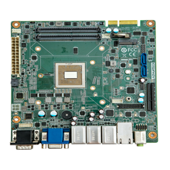
KX-U6780A 2.7GHz/ KX-U6580 2.5GHz/KX-6640MA 2.2Hz processor and DDR4 2400/2666 memory up to 32GB. AIMB-Z20 is equipped with one PCIe x4, one PCIe x4 golden finger. Triple display interfaces are provided to allow users to connect monitors to the onboard VGA, LVDS, and DP ports at the same time. -
Page 11: Specifications/规格
Memory/内存 RAM: Up to 32 GB in two 260-pin SO-DIMM sockets supporting dual-channel DDR4 2666 SO-DIMM. AIMB-Z20 supports non-ECC unbuffered DIMMs and does not support any memory configuration that mixes non-ECC with ECC unbuffered DIMMs 内存:支持双通道DDR4 2666 SO-DIMM, 两个260-pin 内存插槽,容量最高支持32GB。... -
Page 12: Graphics/显示
USB port: 6 x USB 3.0 ports on rear, 8 x USB 2.0 ports (6 rear, 2 via header) GPIO: AIMB-Z20 supports 8-bit GPIO from MCU for general purpose control application. PCIe插槽: 1个PCIe x4插槽,一个PCIe Golden finger ... -
Page 13: Jumpers And Connectors/跳线和连接器
重量:0.5kg (1.1 lb) Jumpers and Connectors/跳线和连接器 Connectors on the AIMB-Z20 motherboard link it to external devices such as hard disk drives and a keyboard. In addition, the board has a number of jumpers that are used to configure your system for your application. The tables below list the function of each of the jumpers and connectors. -
Page 14: Board Layout: Jumper And Connector Locations/板卡布局:跳线和连接器位置
CN2_USB1 USB3.0 Type A ,2port ,USB2.0 TypeA,2port SPDIF_OUT1 SPDIF Audio out pin header FPAUD1 Front Panel Audio pin header INV1 LVDS Power Connector Connector for LPC VGA1 VGA connector DP connector Serial port: RS-232/422/485(DB9) USB2_1 USB2.0, Type A ,4port LAN1/ LAN2 M.2_E1 M.2 connector AUDIO1... -
Page 15: Block Diagram/框图
MCU_JTAG M.2_E1X Note! 注意! 。 AIMB-Z20 is not compatible with 1U chassis. AIMB-Z20不兼容1U机箱 Block Diagram/框图 Figure 1.3 Block Diagram... -
Page 16: Safety Precautions/安全注意事项
Safety Precautions/安全注意事项 Warning! Always completely disconnect the power cord from your chassis whenever you work with the hardware. Do not make connections while the power is on. Sensitive electronic components can be damaged by sudden power surges. Only experienced electronics personnel should open the PC chassis. -
Page 17: How To Set Jumpers /如何设置跳线
1.8.2 CMOS clear (JCMOS1) /清除CMOS The AIMB-Z20 motherboard contains a jumper that can erase CMOS data. Normally this jumper should be set with pins 1-2 closed. If you want to reset the CMOS data, set JCMOS1 to 2-3 closed for just a few seconds, and then move the jumper back to 1-2 closed. -
Page 18: Atx/At Mode Selection (Jat_Atx)/ Atx/At模式选择
System Memory/系统内存 AIMB-Z20 has two 260-pin memory sockets for DDR4 2666 memory modules with maximum capacity of 64 GB (Maximum 32 GB for each DIMM). AIMB-Z20 only supports non-ECC DDR4 memory modules. Please note that AIMB-Z20 does NOT support registered DIMMs (RDIMMs). - Page 19 automatically released and pulled out along the slot. 要安装内存, 内存金手指侧斜着插进插槽, 然后用手指将内存顺时针往下按, 直到插 槽两侧的金属卡扣扣住为止。拔出时,用手指将插槽两侧的金属卡扣同时向外拨动, 内存就会自动解扣,再顺着插槽拔出即可。...
-
Page 20: Chapter 2 Connecting Peripherals 连接外围设备
Chapter Connecting Peripherals 连接外围设备... -
Page 21: Introduction/介绍
CN2_USB1 are USB 3.1 Gen 1 ports supporting transmission rate up to 5 Gbps. The USB interface can be disabled in the system BIOS setup menu. AIMB-Z20 提供 12 个 USB ports。USB2_1, USB1, and half of CN2_USB1 是 USB 2.0 端口,支持高达 480 Mbps 的传输速率。CN1_USB1 and half of CN2_USB1 是 USB... -
Page 22: Vga Connector (Vga1)And Displayport Connector (Dp1) / Vga 和 Dp 接口
3.1 Gen 1 端口支持高达 5 Gbps 的传输速率。可以在系统基本输入输出系统设置菜 单中禁用通用串行总线接口。 VGA Connector (VGA1)and DisplayPort Connector (DP1) / VGA 和 DP 接口 VGA1 &DP1 The AIMB-Z20 includes VGA and DisplayPort interface that can connect dis-play devices. Pin assignments are detailed in Appendix B. AIMB-Z20 包括 VGA 与 DP 端口接口,可以连接显示设备。引脚分配详见附录二。... -
Page 23: Serial Port (Cn5) / 串口
Serial Port (CN5) / 串口 The AIMB-Z20 offers ten serial ports (two on the rear panel and eight on IO board). Above of CN5 can be configured as RS-232/422/485 by selecting correct device mode for RS-485 under BIOS is necessary (see Chapter 3). These ports can connect to a serial mouse, printer or communications network. -
Page 24: Cpu And System Fan Connector (Cpufan1, Sysfan1) / Cpu和系统风扇连接器
CPU and System Fan Connector (CPUFAN1, SYSFAN1) / CPU和系统风扇连接器 SYSFAN1 CPUFAN1 If a fan is used, this connector supports cooling fans that draw up to 500 mA (6 W). 如果使用风扇,此连接器支持最高 500 毫安(6 W)的冷却风扇。 Front Panel Connector (F_PANEL1) /前面板 连接器... - Page 25 F_PANEL1 There are several external switches and LEDs to monitor and control the AIMB-Z20. You can short-circuit the pin5 and pin6 of F_PANEL1 to turn the motherboard on or off. You can connect a LED to pins 1 and 1 of F_PANEL1 to indicate when the HDD is active.
-
Page 26: Line Out, Mic In Connector (Audio1) / Line Out, Mic In 连接器
Line Out, Mic In Connector (AUDIO1) / Line Out, Mic In 连接器 AUDIO1 Line Out can be connected to external audio devices like speakers or headphones. Mic In can be connected to a microphone. Line Out 可以连接到外部音频设备,如扬声器或耳机。 Mic In 可以连接到麦克风。... -
Page 27: Serial Ata Interface (Sata1 ~ Sata2) / Sata 接口
Serial ATA Interface (SATA1 ~ SATA2) / SATA 接口 SATA1 SATA2 AIMB-Z20 features two high performance serial ATA 3.0 interfaces (up to 600 MB/s) with long, thin, easy-to-run SATA cables. AIMB-Z20 具有两个高性能 SATA 3.0 接口( 最高 600 MB/s ),带有长而细且易于运行的 SATA 线材。... -
Page 28: Pcie X4 Expansion Slot (Cn2) / Pcie X4 扩展槽
The AIMB-Z20 offers one PCIe x4 slots for users to install add-on cards for extension requirements. And AIMB-Z20 also provides a PCIe x4 gold finger that can be paired with its backboard to expand the PCIe x4 Slot from 1 Slot to 2 Slots, and expand the USB2.0 ports from 8 to 10 channels. -
Page 29: Auxiliary 4-Pin Power Connector (Atx12V1) / 辅助 4-Pin 电源连接器
ATX12V1 To ensure that the enough power is supplied to the CPU, one auxiliary 4-pin power connector is available on the AIMB-Z20. ATX12V1 must be used to provide sufficient 12 V power to ensure the stable operation of the system. -
Page 30: Gpio Connector (Cn1_Gpio) / Gpio接口
LPC connector on AIMB-Z20 is reserved for Advantech LPC modules. AIMB-Z20 上的 LPC 连接器是为研华 LPC 模块保留的。 2.12 GPIO Connector (CN1_GPIO) / GPIO接口 CN1_GPIO CN1_GPIO connector on AIMB-Z20 is reserved for GPIO Control. AIMB-Z20上的CN1_GPIO连接器是为GPIO控制保留的。... -
Page 31: Lvds Connector (Lvds1) / Lvds 接口
LVDS Connector (LVDS1) / LVDS 接口 2.13 LVDS1 LVDS1 connector on AIMB-Z20 is reserved for LVDS Panel. AIMB-Z20上的LVDS1连接器是为LVDS显示屏保留的。 Inverter Connector (INV1) / Inverter 接口 2.14 INV1 INV1 connector on AIMB-Z20 is reserved for LVDS Power. AIMB-Z20 上的 INV1 连接器是为 LVDS 供电保留的。... -
Page 32: Lan Connector (Cn4) /Lan 接口
LAN Connector (CN4) /LAN 接口 2.15 The AIMB-Z20 is equipped with two high-performance 1000 Mbps Ethernet LANs. They are supported by all major network operating systems. The RJ-45 jacks on the rear plate provide convenient 1000Base-T operation. AIMB-Z20 配备了两个高性能的 1000 Mbps 以太网局域网。所有主要的网络操作系统都... -
Page 33: Mcu Connector (Mcu_Jtag) /Mcu 接口
AIMB-Z20 配备了一个 M.2 接口。为 M.2 设备预留。 MCU Connector (MCU_JTAG) /MCU 接口 2.17 MCU_JTAG The AIMB-Z20 is equipped with an MCU interface. Provide users with burning, debug functions. AIMB-Z20 配备了一个 MCU 接口。为用户提供烧录,debug 功能。... -
Page 34: Chapter 3 Bios Operation Bios 操作
Chapter BIOS Operation BIOS 操作... -
Page 35: Introduction/介绍
Introduction/介绍 This chapter introduces the basic information of BIOS menu and how to use AIMB-Z20 series BIOS Setup program. With the AMI BIOS Setup program, you can control the specific functions of the computer through the setup BIOS menu. The setup program has multiple menus and submenus. These menu options can be set to control the opening or closing of specific computer functions. - Page 36 Entering BIOS Setup/进入BIOS设置 Power on the computer, press the < DEL > key on the post interface to enter the AMI BIOS Setup program. In the BIOS main interface, you can enter the submenu through < ENTER > to determine the options. 打开计算机电源,按post界面上的提示信息,按<...
- Page 37 Figure 3.3 Main setup screen The Main screen of BIOS program interface is divided into two main frames. The left frame displays all setting options, of which the gray options are not configurable and the blue options can be configured. The right frame will display the description of the corresponding options in the left frame.
- Page 38 3.2.2 Advanced BIOS Features Setup Select the Advanced tab from the AIMB-Z20 setup screen to enter the Advanced BIOS setup screen. You can select any of the items in the left frame of the screen, such as CPU configuration, to go to the sub menu for that item.
- Page 39 Figure 3.5 TPM Settings Security Device Support Enable/Disable Security Device. NOTE: Your Computer will reboot during restart in order to change State of the Device. 启用/ 禁用BIOS支持安全设备。注意:更改设备状态系统需要重启。 3.2.2.2 ACPI Settings...
- Page 40 Figure 3.6 ACPI Settings Enable ACPI Auto Configuration Enables or Disables BIOS ACPI Auto Configuration. 启用/ 禁用BIOS ACPI自动设置。 Enable Hibernation "Enable or Disable" Hibernation (OS/S4 Sleep State). This option may not be applied in some OS. 启用/ 禁用休眠(OS S4 睡眠状态)。该选项在有些 OS 上不生效。 ACPI Sleep State ...
- Page 41 Figure 3.8 Serial Port 1 Configuration Serial Port 1 Configuration – Serial Port "Enable or Disable" Serial Port 1. 启用/ 禁用串行端口1 Serial Port 2 Configuration The function like Serial Port 1. 参照串行端口1设置 Serial Port 3 Configuration The function like Serial Port 1. 参照串行端口1设置...
- Page 42 Figure 3.9 Second Super IO Configuration AIMB-Z20 supports 2nd super IO F81216TRD COM 1~4. This page of BIOS menu is to set respective serial port configuration. AIMB-Z20支持第二颗 super IO F81216TRD COM 1~4。BIOS菜单的这一页用于设置 F81216TRD的串行端口。 Figure 3.10 Serial Port 1 Configuration ...
- Page 43 Refer to Serial Port 1 Configuration. 参照串行端口1设置 3.2.2.5 F81803 Super IO Configuration Figure 3.11 Second Super IO Configuration AIMB-Z20 supports 3nd super IO F81803 COM 1~2. This page of BIOS menu is to set respective serial port configuration. AIMB-Z20支持第三颗 super IO F81803 COM 1~2。BIOS菜单的这一页用于设置...
- Page 44 Figure 3.12 Serial Port 1 Configuration Serial Port 1 Configuration – Serial Port "Enable or Disable" Serial Port 1. 开启或关闭串行端口1. –Change Settings Select an optimal settings for Super IO Device. 为设备选择最佳配置 –Mode Selection Selects the serial port mode (RS232/RS422/RS485). The default mode is "RS-232". 选择串行端口模式...
- Page 45 Figure 3.13 Serial Port 2 Configuration Serial Port 2 Configuration – Serial Port "Enable or Disable" Serial Port 2. 开启或关闭串行端口2. –Change Settings Select an optimal settings for Super IO Device. 为设备选择最佳配置 3.2.2.6 Hardware Monitor This page displays various parameters to monitor system hardware status. Number of fans and VIN voltages are updated dynamically based on hardware.
- Page 46 Figure 3.14 PC Health Status Smart Fan Mode Configuration –CPU FAN Mode Smart CPUFAN Mode Select 智能风扇SYSFan 1模式选择。默认为手动模式。 CPUFAN DC/PWM 1 Fan will work with this Manual PWM Value 当风扇模式选择为手动模式时,该选项显示。手动设置风扇 PWM 值,使风扇按此 PWM 运行。 CPUFAN Temperature 1 CPUFAN DC/PWM 2 Fan will work with this Manual PWM Value 当风扇模式选择为手动模式时,该选项显示。手动设置风扇...
- Page 47 当风扇模式选择为手动模式时,该选项显示。手动设置风扇 PWM 值,使风扇按此 PWM 运行。 CPUFAN Temperature4 Input the CPUFAN Temperature3 CPUFAN DC/PWM 5 Fan will work with this Manual PWM Value 当风扇模式选择为手动模式时,该选项显示。手动设置风扇 PWM 值,使风扇按此 PWM 运行。 3.2.2.7 MCU Configuration Figure 3.15 MCU Configuration 3.2.2.8 CPU Configuration This page displays the options available in CPU Configuration. 此页面显示CPU Configuration中可用的选项。...
- Page 48 Figure 3.16 CPU Configuration Enhance power saver SMRR TRD Echo Round-Robin Mechanism CPU Threshold low value CPU Threshold high value AVX Supported Tsc deadline mode Execute Disable(XD) CPU Processor C State 3.2.2.9 Virtualization Configuration...
- Page 49 Figure 3.17 Virtualization Configuration 3.2.2.10 PCI Subsystem Settings Figure 3.19 PCI Subsystem Settings 3.2.2.11 USB Configuration This option allows the user to view and configure the settings of the USB configuration parameters.
- Page 50 该选项允许用户查看和配置USB配置参数的设置。 Figure 3.20 USB Configuration Legacy USB Support This is for supporting USB device under legacy OS such as DOS. When choosing "AUTO", the system will automatically detect if any USB device is plugged into the computer . Enable USB legacy mode when a USB device is plugged, and disable USB legacy mode when no USB device is plugged.
- Page 51 “Enable or Disable” USB Mass Storage driver support. 启用/ 禁用USB大容量存储设备的支持。 Port 60/64 Emulation Enables I/O port 60h/64h emulation support. This should be enabled for the complete USB keyboard legacy support for non-USB aware OSes. 启用/ 禁用 I/O 端口 60h/64h 模拟支持。对于不能识别 USB 的操作系统,应启 用此项,以获得完整的USB 键盘传统支持。...
- Page 52 Figure 3.21 CSM Configuration CSM Support "Enable or Disable" CSM Support. 启用或禁用 CSM 支持。默认设置为[Enabled]。 GateA20 Active GateA20 (GA20) can be disabled using BIOS Services. Do not allow disabling GA20; This option is useful when any RT code is executed above 1MB. [Upon Request]:用户可通过...
- Page 53 Boot Option Filter This option filters which ROM type(s) will be available during boot UEFI Only: Allows UEFI boot devices only. Legacy Only: Allows Legacy boot device only. UEFI and Legacy: Allows both UEFI and Legacy. 过滤启动设备类型 UEFI Only: 只允许UEFI启动设备 Legacy Only: 只允许传统启动设备...
- Page 54 3.2.2.13 NVMe Configuration Figure 3.22 NVMe Configuration 3.2.2.14 Network Stack Configuration...
- Page 55 Figure 3.23 Network Stack Configuration-1 Figure 3.24 Network Stack Configuration-2...
- Page 56 Network Stack "Enable or Disable" UEFI Network Stack. Default is ‘Disabled’. 启用/ 禁用 UEFI 网络堆栈。默认设置为[Disabled]。 – Ipv4 PXE Support Enable/Disable IPv4 PXE boot support. This option is only available when Network Stack is enabled. 启用/ 禁用 IPv4 PXE 启动。该选项仅在开启UEFI 网络堆栈后有效。 –...
- Page 57 3.2.3 Chipset Figure 3.25 Chipset This page provides information of the chipset on AIMB-Z20. 本页提供AIMB-Z20 chipset 的信息。 3.2.3.1 North Bridge Figure 3.25 North Bridge...
- Page 58 DRAM Configuration Display memory information 显示内存信息 Figure 3.26 DRAM Configuration Video Configuration Figure 3.27 Video Configuration VGA Share Memory This option determines how much memory is allocated to the graphics card. Users can choose between 64MB, 128MB, 256MB, 512MB and 1024MB, or select the automatic mode, and the system will automatically allocate enough memory to the...
- Page 59 graphics card. 选择显存大小。可以选择64MB, 128MB, 256MB, 512MB and 1024MB,或者选择 自动模式,系统会自动给显卡分配足够显存。 Primary Graphics Adapter Select Primary Graphics Adapter. 选择主显卡 Integrated Graphics (UMA) Integrated Graphics (UMA) Enable or Disable. 启用/ 禁用集成显卡 3.2.3.2 South Bridge Figure 3.28 South Bridge User can configure south bridge parameter. 用户可以设定南桥配置...
- Page 60 Figure 3.29 South USB configuration Usb S4 WakeUp Control Usb S4 Wake Up Enable/Disable selection 启用/ 禁用 USB S4 唤醒功能 Usb OC Enable/Disable Usb OC Enable/Disable selection 启用/ 禁用 USB过流保护功能。 CND003 SATA Controller Select whether to enable or disable SATA controller. 启用/ 禁用...
- Page 61 Security Figure 3.30 Security Select Security Setup from the AIMB-Z20 Setup main BIOS setup menu. All Security Setup options, such as password protection is described in this section. To access the sub menu for the following items, select the item and press <Enter>.
- Page 62 Figure 3.31 Boot Setup Prompt Timeout Directly key in the number, or use the <+> and <-> keys to adjust the number of seconds to wait for setup activation key. 此项允许用户设置提示进入setup界面等待的秒数。默认设置为 [1]。使用<+> 或 <->键可以增加或减少秒数。 Bootup NumLock State Default state for the NumLock key during power on. 此项允许用户选择键盘[NumLock] 键开机时的默认状态。默认设置为[ON]。...
- Page 63 3.2.6 Save & Exit Figure 3.32 Save & Exit Save Changes and Exit When you complete system configuration, select this option to save your changes, exit BIOS setup and reboot the computer so the new system configuration parameters can take effect. Select Exit Saving Changes from the Exit menu and press <Enter>.
- Page 64 Select Yes to discard changes and exit. 选择此项将退出设置且不保存对系统配置的任何修改。 1.请从退出菜单中选择“Discard Changes and Exit” 并按下 <Enter> 键。屏 幕上将出现以下信息: Discard Changes and Exit Setup Now? [Yes] [No] 2.选择 Yes 将放弃修改并退出设置。 Save Changes and Reset When you have completed the system configuration changes, select this option to save the changes and reboot the system, so the new system configuration parameters can take effect.
- Page 65 Chapter C-960 Graphic Device Setup C-960 Graphic 驱动设置...
- Page 66 Before you begin//安装前 To facilitate the installation of the enhanced display drivers and utility software, read the instructions in this chapter carefully. The drivers for the AIMB-Z20 are located on Advantech support website (http://www.advantech.com/support).. Before you begin, it is important to note that most display drivers need to have the relevant software application already installed in the system prior to installing the enhanced display drivers.
- Page 67 3D support delivers an intensive and realistic visual experience. 兆芯处理器嵌入了集成图形控制器。您需要安装VGA驱动程序来启用此功能,它包括 以下功能: 优化的集成图形解决方案:采用C-960 Graphics柔性显示Inter face,支持多功 能显示选项和32位3D图形引擎。三重独立显示、用于扩展和克隆多显示模式 的宽屏平板的增强显示模式以及优化的3D支持提供了密集而逼真的视觉体 验。 Windows Driver Setup/ Windows驱动设置 Enter the Advantech support website, then search product AIMB-Z20. You can see "Graphics" driver inside 进入研华科技网站,然后搜索产品AIMB-Z20。你可以在里面看到“Graphics”驱动程 序。...
- Page 68 Chapter USB3.0 Device Setup USB3.0 驱动设置...
- Page 69 Introduction/介绍 Win7 32&64bit need install USB3.0 Driver. Win 7 32 & 64位需要安装USB3.0驱动程序。 Windows Driver Setup/ Windows驱动设置 Enter the Advantech support website, then search product AIMB-Z20. You can see "USB3.0" driver inside. 进入研华科技网站,然后搜索产品AIMB-Z20。里面可以看到“USB3.0”驱动。...
- Page 70 Appendix I/O Pin Assignments I/O Pin 分配...
- Page 71 LVDS Port (LVDS1) Table B.1: LVDS Port (LVDS1) Signal Signal VDD_LVDS VDD_LVDS VDD_LVDS VDD_LVDS VDD_LVDS VDD_LVDS LVDS1_A0N LVDS1_A4N LVDS1_A0P LVDS1_A4P LVDS1_A1N LVDS1_A5N LVDS1_A1P LVDS1_A5P LVDS1_A2N LVDS1_A6N LVDS1_A6P LVDS1_A2P LVDS1_CLK1N LVDS1_CLK2N LVDS1_CLK1P LVDS1_CLK2P LVDS_SPC1 LVDS_SPD1 LVDS1_A7N LVDS1_A3N LVDS1_A3P LVDS1_A7P +V3.3 LVDS1_VCON LAN Port (CN4) Table B.2: LAN Port (CN4) Signal...
- Page 72 LAN2_EESK_LINK100# LAN1_EESK_LINK100# LAN2_MDI0+ LAN1_MDI0+ LAN2_MDI0- LAN1_MDI0- LAN2_MDI1+ LAN1_MDI1+ LAN2_MDI1- LAN1_MDI1- LAN2_MDI2+ LAN1_MDI2+ LAN2_MDI2- LAN1_MDI2- LAN2_MDI3+ LAN1_MDI3+ LAN2_MDI3- LAN1_MDI3- LAN2_COMG LAN1_COMG LAN2_GND- LAN1_GND- USB 2.0 Type A (USB2_1) Table B.3: USB 2.0 TypeA (USB2_1) Signal Signal USB-3_B USB+3_B GND_4 USB-2_B USB+2_B GND_3 USB-1_B USB+1_B...
- Page 73 Table B.4: USB 3.0 TypeA (CN1_USB1) Signal Signal D-_A D+_A STDA_SSRX-_A STDA_SSRX+_A STDA_SSTX-_A STDA_SSTX+_A D-_B D+_B STDA_SSRX-_B STDA_SSRX+_B STDA_SSTX-_B STDA_SSTX+_A D-_C D+_C STDA_SSRX-_C STDA_SSRX+_C STDA_SSTX-_C STDA_SSTX+_C D-_D D+_D STDA_SSRX-_D STDA_SSRX+_D STDA_SSTX-_D STDA_SSTX+_D USB 3.0 &2.0 TypeA (CN2_USB1) Table B.5.1: USB 2.0 TypeA (CN2_USB1) Signal Signal D-_1...
-
Page 74: Vga Connector (Vga1)
D-_3 D+_3 STDA_SSRX-_3 STDA_SSRX+_3 STDA_SSTX-_3 STDA_SSTX+_3 D-_4 D+_4 STDA_SSRX-_4 STDA_SSRX+_4 STDA_SSTX-_4 STDA_SSTX+_4 USB 2.0 Header (USB1) Table B.6: USB 2.0 Header ( USB1) Signal Signal USB2_DN- USB3_DN- USB2_DP+ USB3_DP+ VGA Connector (VGA1) Table B.7: VGA Connector (VGA1) Signal Signal VGA1_b_R VCC_VGA VGA1_b_G GND_VGA... - Page 75 VGA1_a_DDAT VGA1_b_HS VGA1_FOC_ON VGA1_b_VS VGA1_a_DCLK DP++ Connector (DP1) Table B.8: DP++ Connector (DP1) Signal Signal DDI_CPU_DP1_b_TX0+ DP1_AUX_EN# DDI_CPU_DP1_b_TX0- DP1_AUX+ DDI_CPU_DP1_b_TX1+ DP1_AUX- DDI_CPU_DP1_b_TX1- DP1_HPD_CN DDI_CPU_DP1_b_TX2+ +V3.3_DP1 DDI_CPU_DP1_b_TX2- DDI_CPU_DP1_b_TX3+ DDI_CPU_DP1_b_TX3- RS-232/422/485 & RS-232 Interface (CN5) Table B.9.1: RS-232/422/485 DB-9 Connector (CN5A) Signal COM1_DCD_422TX-_B COM1_RXD_422TX+_A COM1_TXD_422RX+...
- Page 76 COM1_CTS# COM1_RI# Table B.9.2: RS-232/422/485 DB-9 Connector (CN5B) Signal COM2_DCD# COM2_RXD COM2_TXD COM2_DTR# COM2_DSR# COM2_RTS# COM2_CTS# COM2_RI# B.10 Inverter Connector (INV1) Inverter Table B.10: Inverter Connector (INV1) Connector (INV1) Signal +V12 INV1_ENBKL INV1_VBR...
-
Page 77: Low Pin Count Connector (Lpc1)
B.11 CPU and System Fan Power Connector (CPUFAN1, SYSFAN1) Table B.11: CPU and System Fan Power Connector (CPUFAN1, SYSFAN1) Signal +12 V Detect PWMOUT B.12 5*2-pin wafer for Front panel of LED & Power button & System reset button (F_PANEL1) Table B.12: 5*2-pin wafer for Front panel of LED &... -
Page 78: Gpio Connector (Gpio1)
+V3.3 LPCAD0 LPCAD1 -LPCFRAME LPCAD2 SERIRQ LPCAD3 CLK33M_SIO3 PRST_SIO2# CLK33M_SIO2 B.14 GPIO Connector (GPIO1) Table B.14: GPIO Connector (GPIO1) Signal Signal GPIO0 GPIO4 GPIO1 GPIO5 GPIO2 GPIO6 GPIO3 GPIO7 +VCC_GPIO B.15 MCU Connector (MCU_JTAG) Table B.15: MCU Connector (MCU_JTAG) Signal SWCLK SWDIO MCU_NRST#... - Page 79 Signal Signal A_z_MIC2-L GND_A A_z_MIC2-R -EXTSMI A_z_LINE2-R A_MIC2-JD A_FIO_SENSE A_z_LINE2-L A_LINE2-JD B.17 ATX/AT Connector ( JAT_ATX Table B.17: ATX/AT Connector (JAT_ATX) Signal AT_ATX_SEL B.18 CMOS Connector (JCMOS1) Table B.18: CMOS Connector (JCMOS1) Signal VBAT RTCRST# B.19 LVDS Power Connector (JLVDS_VDD) Table B.19: LVDS Power Connector (JLVDS_VDD) Signal +V3.3...
- Page 80 B.20 ATX 24-pin main power connector for system (EATXPWR1) Table B.20: ATX 24-pin main power connector for system (EATXPWR1) Signal Signal +3.3VATX +3.3VATX +3.3VATX -V12 SPS_PS_ON#_R PG _ATX +V5SB +V12 +V12 +3.3VATX B.21 ATX 12V auxiliary power connector for CPU (ATX12V1) Table B.21: ATX 12V auxiliary power connector for CPU (ATX12V1) Signal...
- Page 81 B.22 Serial ATA (SATA1/ SATA2) Table B.22: Serial ATA (SATA1/ SATA2) Signal I_PEXPHYB_TX0+ I_PEXPHYB_TX0- I_PEXPHYB_RX0- I_PEXPHYB_RX0+ B.23 M.2 connector (M.2_E1) Table B.23: M.2 connector (M.2_E1) Signal Signal +V3.3_M2 USB1+ +V3.3_M2 USB1-...
- Page 82 N108034923 N108034920 PCIECLK4P PCIECLK4N PLTRST_Wifi# PCIE_WAKE# +V3.3_M2 +V3.3_M2 B.24 PCIE X4 Connector (CN2) Table B.24: PCIE X4 Connector (CN2) Signal Signal +V12 +V12 +V12 +V12 SMBCK JTAG2 SMBDT JTAG3 +V3.3 JTAG5...
- Page 83 PCIE2__JTAG1 +V3.3 +V3.3SB +V3.3 PCIE_WAKE# PWGOD PCIECLK6P HSOP0 PCIECLK6N HSON0 HSIP0 PRSNT2_1 HSIN0 HSOP1 HSON1 HSIP1 HSIN1 HSOP2 HSON2 HSIP2 HSIN2 HSOP3 HSON3 HSIP3 HSIN3 PRSNT2_2...
- Page 84 No part of this publication may be reproduced in any form or by any means, electronic, photocopying, recording or otherwise, without prior written permission of the publisher. All brand and product names are trademarks or registered trademarks of their respective companies. © Advantech Co., Ltd. 2021...
Need help?
Do you have a question about the AIMB-Z20 and is the answer not in the manual?
Questions and answers