
Related Manuals for Mars Comfort-Aire Century L Series


Summary of Contents for Mars Comfort-Aire Century L Series
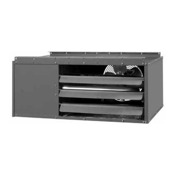
- Page 1 Installation, Operation & Maintenance Manual "L" Series Unit Heaters Low Profile 517.787.2100 • www.marsdelivers.com • www.heatcontroller.com...
-
Page 3: For Your Safety
INSTALLATION INSTRUCTIONS AND PARTS IDENTIFICATION TUBULAR GAS FIRED DIRECT SPARK PROPELLER UNIT HEATERS – FOR COMMERCIAL, INDUSTRIAL AND RESIDENTIAL INSTALLATIONS – ATTENTION: READ THIS MANUAL AND ALL LABELS ATTACHED TO THE UNIT CAREFULLY BEFORE ATTEMPTING TO INSTALL, OPERATE OR SERVICE THESE UNITS! CHECK UNIT DATA PLATE FOR TYPE OF GAS AND ELECTRICAL SPECIFICATIONS AND MAKE CERTAIN THAT THESEAGREE WITH THOSE AT THE POINT OF INSTALLATION. -
Page 4: Table Of Contents
TABLE OF CONTENTS SPECIFICATIONS OPERATION .............. 26 Basic Description ........... 2 GAS INPUT RATE ............27 Performance & Specification Data ..... 4, 5 MAINTENANCE GENERAL SAFETY INFORMATION Servicing & Cleaning ..........28 Installation Codes ..........2, 3 TROUBLESHOOTING GUIDE ......29-33 Special Precautions .......... -
Page 5: General Safety Information
GENERAL SAFETY INFORMATION Failure to comply with the general Make certain that the power source conforms to the safety information may result in extensive electrical requirements of the heater. property damage, severe personal injury, or death. Do not depend upon a thermostat or other switch as sole means of disconnecting power when installing or servicing heater. - Page 6 Table 1 - Performance and Dimensional Data - Tubular 30 thru 120 Propeller Unit Heater Unit Size PERFORMANCE DATA† Input - BTU/Hr. 30,000 45,000 60,000 75,000 90,000 105,000 120,000 (kW) (8.8) (13.2) (17.6) (22.0) (26.4) (30.8) (35.2) Output - BTU/Hr. 24,900 37,350 49,800...
- Page 7 Figure 2 - Dimensional Drawing – Tubular 30 thru 120 Propeller Unit Heater D8597 DIMENSIONS .XXX STANDARD UNITS DIMENSIONS IN PARENTHESIS (XXX) MILLIMETERS Table 2 - Heat Throw Data Standard Unit Heater Applications Distance From UNIT SIZE BTU/Hr Floor to Bottom 30,000 45,000 60,000...
-
Page 8: Installation
INSTALLATION Do not install unit heaters in AIR FOR COMBUSTION: The unit heater shall be installed in a location in which the facilities for ventilation corrosive or flammable atmospheres! Premature failure of, or severe damage to the unit will permit satisfactory combustion of gas, proper venting, and the maintenance of ambient air at safe limits result! under normal conditions of use. -
Page 9: Installation Codes
INSTALLATION (continued) Figure 3 - Hanger Bracket Installation Instructions The Unit Heater may be mounted by fastening the hanging brackets directly to ceiling joists or by suspending from four rods. See Figures 3, 4 and 5. Make certain that the lifting methods used to lift the heater and the method of suspen- sion used in the field installation of the heater are capable of uniformly... -
Page 10: Gas Supply Piping
GAS PIPING To avoid damage or possible personal injury, do not connect gas piping to this unit until a supply line pressure/leak test has been completed. Connecting the unit before completing the pressure/leak test may damage the unit gas valve and result in a fire hazard. Do not rely on a shut-off valve to isolate the unit while conducting gas pressure/leak tests. -
Page 11: Pipe Installation
PIPE INSTALLATION 1. Install the gas piping in accordance with applicable Do not over tighten the inlet gas local codes. piping into the valve. This may cause stresses that 2. Check gas supply pressure. Each unit heater must will crack the valve! be connected to a gas supply capable of supplying its full rated capacity as specified in Table 4. -
Page 12: Electrical Connections
ELECTRICAL CONNECTIONS THERMOSTAT WIRING AND LOCATION: NOTICE: The thermostat must be mounted on a HAZARDOUS VOLTAGE! vertical, vibration-free surface, free from air currents, DISCONNECT ALL ELECTRIC and in accordance with the furnished instructions. POWER INCLUDING REMOTE DISCONNECTS BEFORE Mount the thermostat approximately 5 feet (1.5m) above SERVICING. - Page 13 ELECTRICAL CONNECTIONS (continued) Figure 10A - UT Control Board D8604 Figure 11A - Honeywell Control Board D8605...
- Page 14 ELECTRICAL CONNECTIONS (continued) Figure 10B - Tubular Propeller Units 30-120 with Natural and Propane (LP) Gas with Single Stage Gas Control and UT Control Board NOTICE: See Figures 7, 8, 9, 10B, 11B, for connecting the thermostat to the unit heater. If using a standard low voltage thermostat with a sub-base switch for fan control, connect the G terminal of the thermostat to the G terminal...
- Page 15 ELECTRICAL CONNECTIONS (continued) Figure 11B - Tubular Propeller Units 30-120 with Natural and Propane (LP) Gas with Single Stage Gas Control and Honeywell Control Board NOTICE: See Figures 7, 8, 9, 10B, 11B, for connecting the thermostat to the unit heater. If using a standard low voltage thermostat with a sub-base switch for fan control, connect the G terminal of the thermostat to the G terminal...
- Page 16 VENTING* All unit heaters must be vented! All Venting installations shall be in accordance with the latest edition of Part 7, Venting of Equipment of the National Fuel Gas Code, ANSI Z223.1 (NFPA 54), or applicable provisions of local building codes. All venting of residential tubular unit heaters must comply with CSA International Requirements 10.96 U.S.
-
Page 17: Venting General
VENTING - GENERAL GUIDELINES Vent connectors serving Category I and Category II The following guidelines apply to all categories to follow. heaters shall not be connected into any portion of Table 5 mechanical draft systems operating under positive vent pressure. Vent Systems Termination Clearance Requirements Maintain clearance between the vent pipe and combustible... -
Page 18: Standard Combustion
STANDARD COMBUSTION VERTICALLY VENTED, CATEGORY I - Figure 12 Observe the following precautions when venting the unit: 5. Slope horizontal runs upward from the gas unit heater 1. Use flue pipe of the same size as the flue connection(s) at least 1/4-inch per foot (21mm/m) minimum. on the gas unit heater 4 inches (102mm). - Page 19 Figure 12 - Vertically Vented, Category I D9257 Figure 12A - Double Wall Draft Hood Connector D06880...
- Page 20 STANDARD COMBUSTION HORIZONTALLY VENTED, CATEGORY III - Figures 13A, 14 & 16 Observe the following precautions when venting the unit: 1. Use flue pipe of the same size as the flue combustible materials according to vent pipe connection(s) on the gas unit heater, 4 inches manufacturer’s instructions.
- Page 21 Figure 13A - Category III Horizontal Venting Requirements Using Single Wall Vent Pipe D9259 Figure 13B - Vertically Vented, Category III D9258...
- Page 22 VENTING (continued) Figure 14 D9260 Figure 15 D3619D...
- Page 23 VENTING (continued) Figure 16 D9262 Figure 17 D3662E...
-
Page 24: Separated Combustion
SEPARATED COMBUSTION INSTALLATION - VENTING – CATEGORY III NOTICE: Every Separated Combustion unit to be installed MUST use the Factory available Combustion Air Inlet Kit. If you do not have this kit, contact the manufacturer ASAP to obtain one prior to installation. COMBUSTION AIR 7. - Page 25 SEPARATED COMBUSTION VENTING (continued) 7. The equivalent length of the flue vent system must 4. Use UL 1738 listed single or double wall pipe for the vent system. For installations in Canada, use corrosion not be less than 5 feet (1.5m) and must not exceed resistant and gas-tight, listed vent pipe conforming 30 feet (9m).
- Page 26 Figure 19 - Vertical Intake/Vent Installation D9264 Figure 20 - Horizontal Intake/Vent Installation D9265 Figure 21 - Horizontal Intake/Vent Installation D9266...
-
Page 27: Vertical Termination
SEPARATED COMBUSTION VENTING (continued) NOTICE: Every Separated Combustion unit to be installed MUST use the Factory available Combustion Air Inlet Kit. See installation instructions included with kit for complete list of instructions. If you do not have this kit, contact the manufacturer ASAP to obtain one prior to installation. AIR INLET COLLAR HORIZONTAL TERMINATION Remove screen and mounting plate from air inlet on... -
Page 28: Operation
OPERATION POWER VENTED PROPELLER UNITS DIRECT SPARK IGNITION EXPLANATION OF CONTROLS: 8. The wall thermostat, supplied optionally, is a 1. Each Unit Heater comes equipped with a power temperature sensitive switch that operates the vent system that consists of a power venter motor vent system and ignition system to control the and blower, pressure switch, and sealed flue temperature of the space being heated. -
Page 29: Primary Air Adjustment
PRIMARY AIR ADJUSTMENT Primary air adjustment is made at the factory. No field adjustments are necessary. GAS INPUT RATE Check the gas input rate as follows (Refer to General 2. PROPANE GAS: An exact manifold pressure of 10.0 Safety Information section for metric conversions). inches W.C. -
Page 30: Maintenance
Table 8 High Altitude Deration - United States Manifold Pressure Altitude BTU Output Natural Gas Liquid Propane Feet Meters Inches WC Inches WC Percentage 0-2,000 0-610 2,491 100% 2,001-3,000 611-915 2,292 3,001-4,000 916-1,220 2,092 4,001-5,000 1,221-1,525 1,918 5,001-6,000 1,526-1,830 1,744 6,001-7,000 1,831-2,135 1,594... - Page 31 Table 9 - Tubular Propeller Troubleshooting Guide POSSIBLE CAUSE(S) CORRECTIVE ACTION SYMPTOMS A. Flame pops back. 1. Burner orifice incorrect. 1. Check for proper orifice size. Refer to “Operation”. 2. Low manifold Pressure. 2. Test and reset manifold pressure. B. Noisy Flame. 1.
- Page 32 Table 9 - Tubular Propeller Troubleshooting Guide (continued) POSSIBLE CAUSE(S) CORRECTIVE ACTION SYMPTOMS I. Burner will not shut off. 1. Thermostat located incorrectly. 1. Relocate thermostat away from outside wall or drafts. 2. Improper thermostat wiring. 2. Check thermostat circuit for open and close on terminal strip on heater “R”...
- Page 33 Table 9 - Tubular Propeller Troubleshooting Guide POSSIBLE CAUSE(S) CORRECTIVE ACTION SYMPTOMS R. Cold air is delivered during 1. Incorrect manifold pressure or input. 1. Refer to “Operation”. heater operation. S. High limit tripping. 1. Unit is over fired. 1. Burner orifice may be too large, verify and replace.
-
Page 34: Led Status
Table 10A - Troubleshooting with LED Indicator Assistance for UT Control Board INDICATES CHECK/REPAIR LED STATUS Slow Flash Control OK, no call for heat. Not Applicable Line voltage power can cause product damage, Fast Flash Control OK, call for heat present. Not Applicable severe injury or death. - Page 35 Table 10B - Troubleshooting with LED Indicator Assistance for Honeywell Control Board STATUS CHECK/REPAIR PATTERN Short Flash Control powered (without call for Heat) Not Applicable Heartbeat Call for Heat: normal operations Not Applicable Pressure Switch failed closed 1. Check pressure switch to see if open to start, if not replace switch.
-
Page 36: Identification Of Parts
IDENTIFICATION OF PARTS TUBULAR 30-120 MBH UNIT SIZES Figure 23 Item ItemDescription Vestible Panel/Tube Assembly (Heat Exchanger) Bracket/Gas Train Manifold Burner Assembly *Standard Orifice Natural Gas or Propane (LP) Gas Spark Ignitor Flame Sensor Gas Valve Natural or Propane (LP) Gas Manual Rollout Safety Switch Transformer, 50 VA, 115/24 Air Pressure Switch... - Page 37 IDENTIFICATION OF PARTS TUBULAR 30-120 MBH UNIT SIZES Figure 25 - Propeller Parts Figure 26 - Component Parts Fan Blade Fan Guard D03339 D03339 Motor Hardware Pressure Switch D4430 Hardware D4430 NOTE: No rubber grommets are supplied with the 30 and 45 unit sizes.
-
Page 38: How To Order Replacement Parts
HOW TO ORDER REPLACEMENT PARTS Please send the following information to your local representative: if further assistance is needed, contact the manufacturer’s customer service department. •Unit Number •Serial Number •Part Description and Number as shown in Replacement parts Catalog LIMITED WARRANTY Power Vented Tubular Propeller Unit Heaters 1. -
Page 39: Unit Number Description
LOW PROFILE TUBULAR PROPELLER UNIT NUMBER DESCRIPTION 9 10 11 12 FT FM GT AL GC SV MT DL Digit #1 - Unit Type [UT] Digit #8 - Altitude [AL] L - Low Profile Tubular Propeller L - 0–4,999 feet - Low Altitude Digit #2, 3, 4 - Capacity [CA] Digit #9 - Direct Spark Gas Control [GC] 030 - 30,000 BTU/HR... -
Page 40: Gas Equipment Start-Up
GAS EQUIPMENT START-UP Customer ____________________________________ Job Name & Number _________________________ PRE-INSPECTION INFORMATION With power and gas off. Type of Equip: Unit Heater Serial Number _________________________ Model Number __________________________ Name Plate Voltage: _____________ Name Plate Amperage: _____________ Type of Gas: Natural Tank Capacity _______ lbs. - Page 42 1900 Wellworth Ave. • Jackson, MI 49203 517.787.2100 • www.marsdelivers.com • www.heatcontroller.com 7/2016...
Need help?
Do you have a question about the Comfort-Aire Century L Series and is the answer not in the manual?
Questions and answers