Advertisement
Advertisement
Table of Contents

Related Manuals for Growatt ALP 5.0L-E2


Summary of Contents for Growatt ALP 5.0L-E2
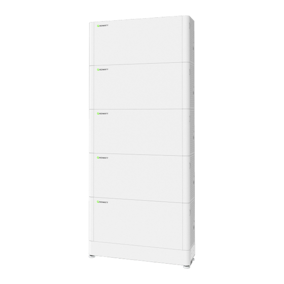
- Page 1 Quick Installation Guide ALP 5.0L-E2 Shenzhen Growatt New Energy Co.,Ltd...
-
Page 2: Installation Environment
Installation environment RH. +5%~+95% Max.+50℃ Min.-10℃ Installation tools The following tools are required to install the PACK: 5mm Allen key Screw Driver Wrench Impact drill Measuring tape Multimeter Marker Dimensions Unit:mm POWER 1.Check 1- 1 Check the Packing List Positive Parallel Power cable*1 Negative Parallel Power cable *1 ALP 5.0L *1 Parallel communication cable *1... - Page 3 left trim cover *1 right trim cover *1 1- 1 Check the accessories ALP 5.0 L Wall bracket Base 2500mm 2000mm 2000mm 2500mm 2000mm 2500mm 2000mm 2500mm 2000mm ALP 5.0L Parallel Cable ALP 5.0L Cable Installation Method Compound Mode Standard wall-mounted installation A*N+B+D Standard floor-mounted installation A*N+C+D...
-
Page 4: Basic Installation Requirements
2.Basic installation requirements Floor-mounted Installation Wall ≥300mm ≥300mm Ground Ground Ground Note: Do not turn the PACK upside down, and ensure that the floor is level. A maximum of 5 battery packs can be stacked. If there are more than 5 of them, please install them in two lines. -
Page 5: Installation
Outdoor installation Wall Wall Note: When installing outdoors, build a sun and rain shade to avoid direct exposure to the sunlight and rain. 4. Installation Hole dimensions (unit: mm) Right Left... - Page 6 Marker Level Install the connecting pieces on both sides Keep the battery level. and tighten the two screws. Mark the hole position to fix the battery Install the anti-tipping plates on both sides and module. tighten the two screws. Dia 8.0mm M6 expansion screw Marking-off...
- Page 7 Wall-mounted Installation (unit: mm) Hole dimensions Right Left Marker Level Keep the bracket level. Mark the mounting hole positions on the wall for installing the bracket. Drill eight holes.
- Page 8 Marker Install the battery module on the wall bracket. Fix the wall bracket to the wall. Install the anti-tipping plates on both sides and Mark the hole position to fix the battery tighten the two screws. module. Dia 8.0mm M6 expansion screw Marking-off 90°...
-
Page 9: Electrical Connection
5.Electrical Connection Communication terminal Battery side Battery side Wire side Wire side Power terminal Battery side Battery side Wire side Wire side Press Single-column wiring TO PCS ALP 5.0L Cable Note: 1.The battery is not allowed to be installed in the running state, and all the RUN lights of battery modules should be off before installation. - Page 10 Two-column wiring TO PCS ALP 5.0L Cable ALP 5.0L Cable Cable raceway Install the Trim Cover BAT- Top battery BAT+ Bottom battery...
- Page 11 6.Power on and off the Battery Power On POWER 1.Press the POWER button for 3 seconds. Observe the LED indicator on the panel. 2.The battery LED indicator lights up to indicate that the battery has been turned on. Power on the PACK by pressing the power button(t>3S) Serial Procedures Acceptation criteria...
-
Page 12: Service And Contact
Press the power button to turn off the PACK and five LED lights will flicker three times. If multiple packs are connected in parallel, turning off one of the PACKs will 7.Service and contact Shenzhen Growatt New Energy Co., Ltd. 4-13/F, Building A, Sino-German (Europe) Industrial Park, Hangcheng Blvd, Bao'an District, Shenzhen, China +86 755 2747 1942 service@ginverter.com...
Need help?
Do you have a question about the ALP 5.0L-E2 and is the answer not in the manual?
Questions and answers