Table of Contents

Related Manuals for Growatt APX86H-S1-US Series


Summary of Contents for Growatt APX86H-S1-US Series
- Page 1 APX 86~200H-S1-US High Voltage Battery System Download User Manual Manual Growatt USA, Inc. 9227 Reseda Blvd, #435 Northridge, CA 91324, USA. +1-866-686-0298 usaservice@ginverter.com us.growatt.com GR-UM-395-A-00 (PN:044.0126300)
- Page 2 About This Document This document introduces the APX 86 200H-S1 -US High Voltage Battery System (APX for short) in terms of its installation, electrical connection, operation, commission, maintenance, and troubleshooting. Before installing and operating the APX system, ensure that you are familiar with the product features, functions, and safety precautions provided in this document.
-
Page 3: Table Of Contents
Table of Contents 6 Powering on/off the Battery System ........35 1 Product Overview ..............1 6 1 Powering on the Battery System ..............35 1.1 Intended Use ....................... 1 Powering off the Battery System ..............36 1.2 Appearance......................1 7 Maintenance ................37 1.2.1 APX 1000140-C1-US (Control Module) ............ -
Page 4: Product Overview
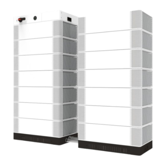
1 Product Overview Designation Description 1.1 Intended Use The APX 86~200H-S1-US High-voltage Battery System can supply power to loads POWER Power button working with WIT 28-55kW or WIT 50-100kW Hybrid Inverter when needed. Make Switch DC switch sure to purchase the suitable Hybrid Inverter. If 6-8 battery modules are configured, please select the WIT 28-55kW model. - Page 5 Dimensions (unit: mm) Function Function description Display SOC Display current SOC in a circle progress bar Light bars light up one by one clockwise during Display the BM charging; charge/discharge Light bars go out one by one anticlockwise during state & the system discharging (the number of light bars corresponds upgrade state to the system SOC with each representing 2% SOC).
-
Page 6: Apx 14.3P-B1-Us (Battery Module)
1.2.2 APX 14.3P-B1 (Battery Module) Dimensions (unit: mm) The APX 14.3P-B1 Battery Module (BM) consists of battery cells, DC-DC converter, mechanical parts, Battery Management Unit (BMU) as well as power and communication terminals. The appearance of the product is shown below. 10 9 Figure 1-6: Appearance of the APX 14.3P-B1 Designation... -
Page 7: Working Principle And Function
The APX battery system communicates with the hybrid inverter via CAN communication. Growatt shall not be liable for any consequence of the following circumstances: Ÿ Damage during the transportation by the customer. -
Page 8: Safety Precautions
2.2 Safety Precautions 2.3 Label Description 2.2.1 Environment Requirements Symbols Description Ø The ambient temperature should not exceed 50°C and keep the battery away from heat sources. Do not dispose of the product together with the household waste Ø Do not install or use the battery in a wet place with moisture or liquids, such as in but in accordance with the disposal regulations for electronic the bathroom. -
Page 9: Emergency Responses
Figure 2-1: Nameplate If the battery system is soaked or submerged in water, do not Flood touch the batteries to avoid electric shock. Contact Growatt or emergency your distributor immediately for technical assistance. The shell damage requires extra attention as it is high risk. Do... -
Page 10: Storage And Transportation
3 Storage and Transportation Installation & Cable Connection 4 3.1 Storage Requirements Ø Read through this manual before installation to get familiar with the product information and safety precautions. Ø Handle the batteries according to the signs on the packing case. Ø... -
Page 11: Installation Tools
≥300mm Do not place the battery pack upside down. WARNING Ø When installing the battery system outdoors, it is recommended to install a sun shelter over the system to avoid exposure to direct sunlight; otherwise, the ≥300mm battery system might fail to charge or discharge normally, or it might even 800≤d≤1000mm ≥600mm Wall... -
Page 12: Installation Procedures
4.3.1.1 Check the components of the APX Battery System in different capacities Auxiliary tool Electric drill Forklift APX 1000140-C1-US(entire unit) APX 14.3P-B1-US(entire unit) Lifting platform Crane T type socket wrench It is recommended to wear the following safety gear when handling the battery system. -
Page 13: Floor-Mounted Installation
4.3.1.2 Check the package of the Control Module The Control Module model for the APX High Voltage Battery System is APX 1000140-C1-US. Anti-tipping & grounding piece*4 Front Cover of the BM M6 screw*16 Figure 4-5: Components included in the package of the Battery Module Cables connecting the CM with the BM The Control Module and the Battery Module are indispensable Ø... - Page 14 Step 1: Install the battery base: 2N·m M12X120 φ16mm 18mm Figure 4-8: Placing the battery module Step 4: Install the 4 anti-tip & grounding connecting pieces between the BM and 2.5 inch pipe joint Remove the panel at the front and back of the the base to avoid tip-overs and for grounding purpose.
-
Page 15: Electrical Connection
4.4 Electrical Connection Step 6: Connect the 4 anti-tip & grounding connecting pieces between the BM and the CM. Therefore, it is necessary to install the anti-tip components properly. Do not forget to wear the ESD wrist strap, safety gloves and goggles. - Page 16 172.03 kWh 157.69 kWh Figure 4-14: Connecting the power cables between CM and hybrid inverter 186.369 kWh 200.70 kWh Figure 4-13: Installation diagram of the battery system with a capacity of 129.02 kWh to 200.7 kWh Note: When configuring the Battery Modules in two columns, please purchase two bases and the extension cables for series connection, which include the power cable, Figure 4-15: Connecting the communication cables and the AC the communication cable and the PE cable.
- Page 17 B. APX 14.3P-B1 (Battery Module) wiring Figure 4-17: Connecting the communication cables between CM and BM Figure 4-18: Connecting the power Figure 4-19: Connecting the cables between BMs communication cables between BMs Ø Please pay attention to the color of the connectors when connecting power cables.
- Page 18 Step 2: Connect external cables of the battery system. The last battery module refers to the one furthest from the Ø BM 1 BM 2 Control Module. Ø Please pay attention to the color of the connectors when connecting power cables. Only connectors with the same color Notice can be connected.
- Page 19 BM 1 BM 2 Step 3: Connect external cables between the CM and the hybrid inverter. OUT2 OUT2 OUT1 OUT1 OUT1 OUT2 Long cable to the left OUT1 OUT2 OUT1 OUT2 B+ to B- OUT2 OUT1 OUT1 OUT2 2N·m OUT1 OUT2 OUT1 OUT2...
-
Page 20: Terminal Connection 5
Terminal Connection 5 Step4: Reinstall the front and back panels of the base. 5.1 Power terminal 90° 90° press "Click" 2N·m Figure 5-1 Note: Ensure that the terminal is audibly snapped into place (a “click” sound) and the orange/black button pops up, which indicates a secure connection. Improper connection might cause damage to the system. -
Page 21: Powering On/Off The Battery System
6 Powering on/off the Battery Turn the DC switch to ON , and then press the "Power" button (1s<t<2s) System Procedure Acceptance criteria Connect the battery and the Make sure the wiring harnesses are Personnel who install and operate the Battery System must Ø... -
Page 22: Maintenance
7 Maintenance 7.4 Troubleshooting 7.1 Preparation After the system is powered off, the remaining electricity and heat exist in the Indicator chassis, which may cause electric shocks or burns. Therefore, wait 10 minutes Description Cause Measures after the system is powered off and wear protective gloves during operation. 1.There is no safety risk. -
Page 23: Technical Specifications 8
Technical Specifications 8 Indicator 8.1 APX 1000140-C1-US ( Control Module ) Description Cause Measures Items Specifications The power Check whether the power Model APX 1000140-C1-US cable is Power cable cable between the Control disconnected BAT+/BAT- voltage range 250V-950V disconnected Module and the Battery from the Module is securely connected. - Page 24 Formula for calculating the rated capacity of the battery system(EVE): Rated capacity of a single battery module: 252Ah N(Number of modules connected in series): 6-14 IFp74/176/209[(16S)NS]M/-10+50/95 Growatt USA, Inc. 9227 Reseda Blvd, #435 Northridge, CA 91324, USA. +1-866-686-0298 usaservice@ginverter.com us.growatt.com...
Need help?
Do you have a question about the APX86H-S1-US Series and is the answer not in the manual?
Questions and answers