Advertisement
Advertisement
Table of Contents

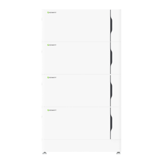
Summary of Contents for Growatt ALP 5.0L-E2 US
- Page 1 Quick Installation Guide ALP 5.0L-E2 US Growatt New Energy...
-
Page 2: Installation Environment
185mm 710mm (27.95in) (7.28in) 1.Check 1- 1 Check the Packing List Positive Parallel Power cable*1 Negative Parallel Power cable *1 ALP 5.0L-E2 US *1 Parallel communication cable *1 Parallel ground cable*1 Warranty card Certificate of conformity Quick installation Manual *1... -
Page 3: Basic Installation Requirements
1- 1 Check the accessories ALP 5.0 L-E2 US Wall bracket Base 1800mm (70.87in) 2000mm(78.74in) 2000mm 1800mm (70.87in) 2000mm(78.74in) 2700mm (106.30in) 2000mm(78.74in) 1800mm (70.87in) 2000mm(78.74in) ALP 5.0L Parallel Cable ALP 5.0L Cable Installation Method Compound Mode Standard wall-mounted installation A*N+B+C+D Standard floor-mounted installation A*N+C+D Wall-mounted battery system stacked in two lines... - Page 4 Outdoor installation Wall Wall Note: When installing outdoors, avoid direct exposure to sunlight and rain. Install under an eave or build a sun and rain shade. Floor-mounted Installation Wall ≥300mm ≥300mm (11.81in) (11.81in) Ground Ground Ground Note: Do not turn the PACK upside down, and ensure that the floor is level. A maximum of 4 battery packs can be stacked.
-
Page 5: Installation
3. Introduction to the battery operation panel nameplate label label label LINK -IN CAN communication PCS CAN communication Negative terminal LINK-OUT CAN communication Positive terminal GND terminal USB interface Power Button Cluster-out communication Cluster-in communication 4. Installation Floor-mounted Installation Note: You can connect the battery and inverter in two ways. For top cable routing, you should use fixed anti-tip connecting pieces during installation;... - Page 6 Place the first battery module onto the base. Secure the connecting pieces on both sides Attach the anti-tip plate to the back cover of the second battery module using the M4*9 screws Stack the second battery module onto the first one, then attach it by securing the connecting pieces on both sides using the M4*8 screws Attach the anti-tip plate to the wall using the M8*95 self-tapping screw Stack the third battery module onto the second one, then fix it by securing the connecting...
- Page 7 Wall-mounted Installation Stick the paper template for drilling holes onto the wall and keep it level. Please select the appropriate installation dimensions (12 in, 16 in, 20 in or 24 in), and mark the hole positions using a marker Attach the mounting bracket to the wall using the M8*95 screws Place the base onto the mounting bracket Insert the four M6*20 screws into the holes on the base, then tighten them with...
-
Page 8: Electrical Connection
Stack the third battery module onto the second one, then secure the connecting pieces on both sides Attach the anti-tip plate to the back cover of the fourth battery module using the M4*9 screws Stack the fourth battery module, then attach it by securing the connecting pieces on both sides using the M4*8 screws Attach the anti-tip plate to the wall using the M8*95 self-tapping screw 5. - Page 9 Note: Install the upper sealing plate before installing the trim cover. BAT+ BAT+ BAT- BAT-...
- Page 10 Single-column wiring TO PCS TO PCS ALP 5.0L Cable ALP 5.0L Cable BAT+ BAT+ BAT- BAT- Top cable routing Rear cable routing Note: 1. The battery should not be installed in the running state, and all the RUN lights of battery modules should be off before installation.
- Page 11 Two-column wiring BAT- BAT+ ALP 5.0L Parallel cable...
-
Page 12: Service And Contact
Press the power button to turn off the PACK and five LED lights will flicker three times. If multiple packs are connected in parallel, turning off one of the PACKs will shut down the whole battery system. 7.Service and contact Growatt USA, Inc. 9227 Reseda Blvd, #435 Northridge, CA 91324, USA. +1-866-686-0298 usaservice@ginverter.com W: us.growatt.com...


Need help?
Do you have a question about the ALP 5.0L-E2 US and is the answer not in the manual?
Questions and answers