
Related Manuals for Soler & Palau RenewAire GR Series


Summary of Contents for Soler & Palau RenewAire GR Series
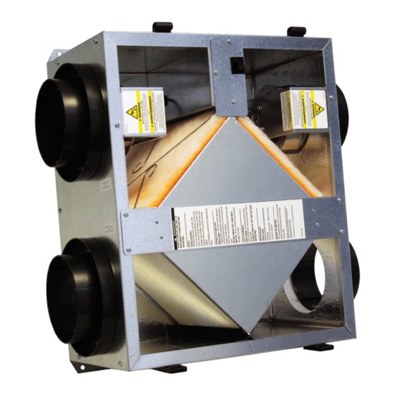
- Page 1 GR & EV SERIES ERV Installation, Operation and Maintenance Manual GR90 EV90 Model: EV90 Painted Case Low Voltage Controls Line Cord Model: GR90 Galvanized Case Line Voltage No Line Cord...
- Page 2 GR90, EV90 WARNING WARNING RISK OF FIRE, ELECTRIC SHOCK, OR INJURY. There is no known safe level of cigarette smoke. Any venti- lation system may provide noticeable improvement in spaces OBSERVE ALL CODES AND THE FOLLOWING: where cigarettes are smoked, but it cannot be expected to pro- 1.
-
Page 3: Owner Information
OWNER INFORMATION GR90, EV90 READ AND SAVE THIS MANUAL/LIRE ET CONSERVER CE MANUEL NOTICE This manual has space for recording operating settings at time of unit commissioning that must be completed by the installer. See Sections 5.1 and 5.2 of this manual. Information that is recorded is specific to just one ERV. -
Page 4: Table Of Contents
TABLE OF CONTENTS GR90, EV90 1.0 OVERVIEW 3.5 CONTROLS ............10 3.5.1 Installing Controls ............. 10 1.1 DEFINITIONS ............5 4.0 OPERATION 1.2 DESCRIPTION ............5 1.2.1 Purpose of an ERV System ..........5 4.1 STARTING UP THE UNIT ........12 1.2.2 When Should You Use Your ERV? .........5 4.2 VERIFYING UNIT PERFORMANCE ......12 1.2.3 Using an ERV with Air-Conditioning ........5 4.2.1 Airflow ................ -
Page 5: Overview
OVERVIEW GR90, EV90 1.0 OVERVIEW 1.1 DEFINITIONS Energy Exchange System: Insulation: Cross flow fixed-plate enthalpic energy 1" foil-faced EPS foam throughout. NOTE: This unit is exchange core: engineered, proprietary Blower/Motor: an Energy Recovery resin-media composite. Moderates both Ventilator, or ERV. Two high efficiency motorized impeller temperature and humidity extremes. -
Page 6: Location Of The Unit
UNIT PLACEMENT GR90, EV90 2.2 LOCATION OF THE UNIT Select a location so that: The supply air intake vent from the outside is placed a minimum of ten feet from any other contaminated exhaust vent, and is at least 30" long. The two ducts to the outside are as short and straight as possible, for the best performance from the system. -
Page 7: Duct Sizes
UNIT PLACEMENT GR90, EV90 The Exhaust Air Duct and the Outside Air Duct connect the unit to the outside. Flexible insulated duct is typically used. 2.3.1 Duct Sizes Exhaust Air & Outside Air (EA & OA): 6" round insulated duct, 8" round insulated duct may be used to maintain maximum airflow. Supply Air &... - Page 8 UNIT PLACEMENT GR90, EV90 NOTE: ERV blower may be operated separate from fur- nace blower. FIGURE 2.4.0 SEPARATE ROOM AIR PICK-UP—SUPPLY AIR TO FURNACE RETURN AIR TRUNKLINE NOTE: ERV blower may be operated separate from fur- nace blower. *Use caution to introduce info@solidworks.com SA at low velocity and where good mixing will oc-...
-
Page 9: Installation
INSTALLATION GR90, EV90 3.0 INSTALLATION 3.1 MOUNTING THE UNIT NOTE: The door is UNIT MAY BE INSTALLED IN ANY ORIENTATION equipped with slide- Orient the unit for the simplest duct layout and connections. off hinges. For the homeowner’s convenience MOUNT THE EV90 ON A CONCRETE FOUNDATION WALL it is helpful to orient the Mount hanging bracket to the wall with appropriate concrete anchors. -
Page 10: Installing Return Air Ducts
INSTALLATION GR90, EV90 3.4 INSTALLING RETURN AIR DUCTS CAUTION All the stale air returns are connected by ducts to the unit. Generally, empty stud cavities are Do not place any stale air used for returns as is often done with cold air returns for the furnace, using standard duct returns in garages. - Page 11 INSTALLATION GR90, EV90 The schematic below (Figure 3.5.0) shows a typical control system: a PTL percentage timer plus two PBL push-button controls. Up to (6) PBL Controls, wired in parallel, may be used. Only (2) PBL Controls can be directly connected to the PTL Control. Wire any additional PBLs in parallel with the first two.
-
Page 12: Operation
OPERATION GR90, EV90 4.0 OPERATION 4.1 STARTING UP THE UNIT Inspect your installation to be sure all duct work is correctly installed and sealed, that filters are in place, and controls (if any) are connected. Shut and latch the door to the unit. Provide 115 VAC to the unit. -
Page 13: Measuring Cross Core Static Pressure
OPERATION GR90, EV90 4.4 MEASURING CROSS CORE STATIC PRESSURE NOTE: The tubing The individual differential static pressures (DP) are measured using the installed pressure ports should extend in located in the front of the units core access doors. the pressure port approx. -
Page 14: Maintenance
MAINTENANCE GR90, EV90 5.0 MAINTENANCE WARNING RISK OF FIRE, ELECTRIC Keep your ERV performing at its best by cleaning it as described below. SHOCK, OR INJURY. 5.1 TO CLEAN THE ENERGY EXCHANGE ELEMENT Before servicing or cleaning the unit, unplug 1. -
Page 15: Service Parts
FACTORY ASSISTANCE GR90, EV90 5.5 SERVICE PARTS FIGURE 5.5.0 SERVICE PARTS 6.0 FACTORY ASSISTANCE In the unlikely event that you need assistance from the factory for a specific issue, make sure that you have the information called for in the Unit Information page in the front of this manual. The person you speak with at the factory will need that information to properly identify the unit. - Page 16 About RenewAire For over 40 years, RenewAire has been a pioneer in enhancing indoor air quality (IAQ) in commercial and residential buildings of every size. This is achieved while maximizing sustainability through our fifth-generation, static-plate, enthalpic-core Energy Recovery Ventilators (ERVs) that optimize energy efficiency, lower capital costs via load reduction and decrease operational expenses by minimizing equipment needs, resulting in significant energy savings.
Need help?
Do you have a question about the RenewAire GR Series and is the answer not in the manual?
Questions and answers