
Related Manuals for Soler & Palau TRe Series


Summary of Contents for Soler & Palau TRe Series
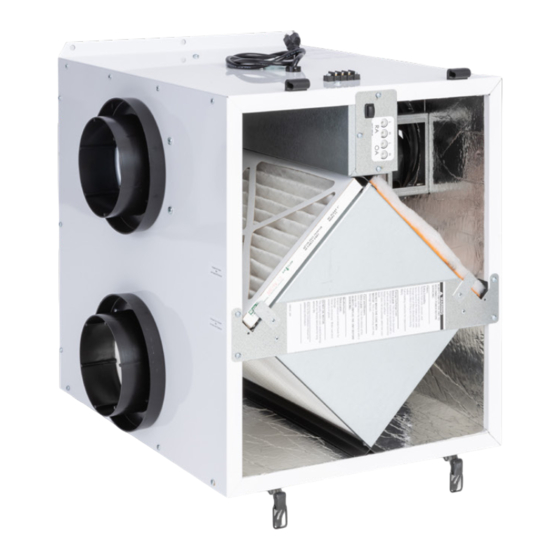
- Page 1 TRe90/H, TRe200, AND TRe300 ERV INSTALLATION, OPERATION & MAINTENANCE MANUAL FOR SINGLE/MULTI-FAMILY APPLICATIONS Model: TRe300, TRe200, and TRe90 shown WWW.SOLERPALAU-USA.COM...
- Page 2 TRe-Series CAUTION CAUTION RISK OF ELECTRIC SHOCK OR EQUIPMENT DAMAGE RISK OF INJURY FROM FALLING OBJECTS Whenever electrical wiring is connected, disconnected or Installation of this unit requires hoisting hardware overhead changed, the power supply to the ERV and its controls must and working directly beneath heavy objects during the be disconnected.
- Page 3 OWNER INFORMATION TRe-Series READ AND SAVE THIS MANUAL/LIRE ET CONSERVER CE MANUEL NOTICE This manual has space for recording operating settings at time of unit commissioning that must be completed by the installer. See Sections 5.1 and 5.2 of this manual. Information that is recorded is specific to just one ERV.
-
Page 4: Table Of Contents
TABLE OF CONTENTS TRe-Series 1.0 OVERVIEW 5.0 OPERATION 1.1 DESCRIPTION ............6 5.1 MANOMETER READINGS AT COMMISSIONING ..19 1.2 OPERATING MODES ..........6 5.2 AIRFLOW READINGS AT COMMISSIONING ....19 5.2.1 Conversion of Pressure Drop to Airflow ......19 1.3 UNIT WEIGHTS ............7 5.2.2 Continuous Mode (low speed) ...........20 5.2.3 Boost Mode (high speed) ..........20 2.0 COMPONENT DESCRIPTION... - Page 5 TABLE OF CONTENTS TRe-Series TABLE OF ILLUSTRATIONS Figure 1.2.0 TRe Cutaway View ............6 Figure 2.1.0 Pressure Port Locations ..........7 Figure 2.4.0 Airstream Illustration ..........9 Figure 2.4.1 Separate Return Air Pick-up—Supply Air to Furnace Return Air Trunk ............9 Figure 2.4.2 Separate return Air and Supply Air ......9 Figure 2.4.3 Furnace Return Air Back into Return Air ....9 Figure 2.4.4 Furnace Return Air Back into Supply Air ....9 Figure 2.6.0 TRe Filter Locations ..........
-
Page 6: Overview
OVERVIEW TRe-Series 1.0 OVERVIEW 1.1 DESCRIPTION The TRe ERVs are multi-speed air-to-air energy recovery ventilators that are designed for residential application and have multiple installation options. They can be suspended from floor joists, or they can be mounted on a wall or other object. Each type of installation can be NOTE: This unit is accomplished by a single person. -
Page 7: Unit Weights
COMPONENT DESCRIPTION TRe-Series 1.3 UNIT WEIGHTS The hanging weight of each TRe90/H is approximately 32 pounds. The hanging weight of each TRe200 is approximately 36 pounds. The hanging weight of each TRe300 is approximately 52 pounds. The shipping weight of each TRe90/H is approximately 38 pounds. The shipping weight of each TRe200 is approximately 48 pounds. -
Page 8: Ducts
COMPONENT DESCRIPTION TRe-Series 2.4 DUCTS IMPORTANT It is important to understand and use the equipment airstream terminology as it is used in NOTE: If you wish to this manual. The airstreams are defined as: install the unit in an attic or other uncon- Outside Air (OA): Air taken from the external atmosphere and, therefore, not previously ditioned space, you must circulated through the system. -
Page 9: Figure 2.4.0 Airstream Illustration
COMPONENT DESCRIPTION TRe-Series OUTSIDE AIR RETURN AIR (INTO UNIT) (FROM OCCUPIED SPACE) SUPPLY AIR EXHAUST AIR (TO OCCUPIED SPACE) (TO OUTDOORS) FIGURE 2.4.0 AIRSTREAM ILLUSTRATION NOTE: ERV blower www.renewaire.com (800) 627- 4499 support@renewaire.com may be operated separate from furnace blower. FIGURE 2.4.1 SEPARATE RETURN AIR PICK-UP—SUPPLY AIR TO FURNACE RETURN AIR TRUNK NOTE: ERV blower may be operated... -
Page 10: Enthalpic Core
COMPONENT DESCRIPTION TRe-Series 2.5 ENTHALPIC CORE NOTE: The cores Each TRe has a static-plate, cross-flow core separates the outgoing, polluted indoor airstream used in all ERVs are from the incoming supply airstream—while simultaneously transferring total energy (heat and static plate enthalpic water vapor) between the two. -
Page 11: Unit Placement
UNIT PLACEMENT TRe-Series 3.0 UNIT PLACEMENT NOTE: If you wish to RenewAire recommends installation of the TRe by a professional HVAC installer with knowledge install the unit in an of local building codes who is able to properly balance the air streams prior to use. The TRe can attic or other be installed by one person. -
Page 12: Ac Power Source
INSTALLATION TRe-Series 3.3 AC POWER SOURCE 3.3.1 TRe90, TRe200, TRe300 Power requirements: 120VAC, 3.0 amps The TRe90, TRe200, and TRe300 have an integral 34" long power supply cord. The installer must provide a standard, grounded 120VAC outlet in the proximity of the ERV. Check all local codes. -
Page 13: Factory-Recommended Low-Voltage Service Entry
INSTALLATION TRe-Series 4.3 FACTORY-RECOMMENDED LOW-VOLTAGE SERVICE ENTRY All low-voltage connections are made on the exterior of the unit on the low-voltage terminal strip. Field-installed low-voltage wiring does not enter the unit. 4.4 ATTACHING DUCTS NOTE: Airflow Ducts are to be fabricated and installed per SMACNA guidelines. Use a combination of zip ties, volumes can be UL-181—rated duct mastic and then secure the duct from slipping off by means of a screw, changed at any time... -
Page 14: Figure 4.5.0 Pressure Port Locations
INSTALLATION TRe-Series USE THESE TWO PRESSURE PORTS TO CHECK PRESSURE DROP FOR THE OA AIRSTREAM USE THESE TWO PRESSURE PORTS TO CHECK PRESSURE DROP FOR THE RA AIRSTREAM FIGURE 4.5.0 PRESSURE PORT LOCATIONS www.renewaire.com (800) 627- 4499 support@renewaire.com Verify the unit has clean filters in place. Open the pressure port caps for the OA airstream and then insert the tubing into the openings about 1". -
Page 15: Wiring Schematics
INSTALLATION TRe-Series 4.6 WIRING SCHEMATICS FIGURE 4.6.0 TRe WIRING SCHEMATIC 1.800.627.4499... -
Page 16: Figure 4.6.1 Tre Hard-Wired Wiring Schematic
INSTALLATION TRe-Series FIGURE 4.6.1 TRe HARD-WIRED WIRING SCHEMATIC 1.800.627.4499... -
Page 17: Low-Voltage Wiring Diagrams
INSTALLATION TRe-Series 4.7 LOW-VOLTAGE WIRING DIAGRAMS 4.7.1 Single Speed Mode CONTINUOUS When plugged in, the unit will run constantly at Low Speed. If the unit is to operate constantly at a single airflow, adjust the OA and RA low speed potentiometers to the desired airflow as described in section 4.6. -
Page 18: Damper Installation For Continuous Erv Operation
INSTALLATION TRe-Series 4.8.1 Damper installation for Continuous ERV Operation If the ERV is set up to provide continuous airflow, a 24V damper can be wired to the 24VAC and COM terminals on the unit terminal block. The damper will open whenever the unit has 120VAC power and close when power is lost. -
Page 19: Operation
OPERATION TRe-Series 5.0 OPERATION 5.1 MANOMETER READINGS AT COMMISSIONING Return Air Pressure Port In. w.g.: Pressure Drop: Exhaust Air Pressure Port In. w.g.: Outside Air Pressure Port In. w.g.: Pressure Drop: Supply Air Pressure Port In. w.g.: 5.2 AIRFLOW READINGS AT COMMISSIONING 5.2.1 Conversion of Pressure Drop to Airflow See the tables below. -
Page 20: Continuous Mode (Low Speed)
MAINTENANCE TRe-Series TRe90/H TRe200 Pressure Airflow with Airflow with Pressure Airflow with Airflow with Drop MERV 8 MERV 13 Drop MERV 8 MERV 13 (In. W.G.) Filters (CFM) Filters (CFM) (In. W.G.) Filters (CFM) Filters (CFM) TRe300 Pressure Airflow with Airflow with Drop MERV 8... -
Page 21: Recalibration Of Airflows
MAINTENANCE TRe-Series 6.2 RECALIBRATION OF AIRFLOWS Whenever there is a reconfiguration of the heating system in a residence, to include changing damper positions, the fan speed potentiometers on the TRe should be re-calibrated for optimum performance. If the residence undergoes significant structural changes, such as an addition to the home, the TRe should also be re-calibrated. -
Page 22: Troubleshooting
TROUBLESHOOTING TRe-Series 7.0 TROUBLESHOOTING 7.1 INDICATION OF PROBLEM CAUTION Indications of a problem with the ERV may be the perception that fresh air is not being delivered. The first step in resolving an apparent problem with an TRe ERV is to verify that there Many of the troubleshoot- actually is a problem. -
Page 23: Inadequate Or Reduced Airflow From The Tre
FACTORY ASSISTANCE TRe-Series 7.4 INADEQUATE OR REDUCED AIRFLOW FROM THE TRe If the unit has power and both fans are running, use a manometer to check the pressure differential across the core. See Section 4.5 Balancing Airflows in this manual. The results of a pressure differential test will provide correct information on how much air the unit is moving and also how the volume of air compares to when the unit was first installed. - Page 24 (800) 961-7370 FAX: (800) 961-7379 6393 POWERS AVE JACKSONVILLE, FLORIDA 32217 USA WWW.SOLERPALAU-USA.COM CANADA (416) 744-1217 FAX: (416) 744-0887 6710 MARITZ DRIVE, UNIT 7 MISSISSAUGA, ON L5W 0A1, CANADA WWW.SOLERPALAUCANADA.COM 141153_002 (12/23)
Need help?
Do you have a question about the TRe Series and is the answer not in the manual?
Questions and answers