Table of Contents
Advertisement
Quick Links
Instruction Manual
Form 1111
February 2009
1301 Series High-Pressure Regulators
WaRning
!
Failure to follow these instructions or
to properly install and maintain this
equipment could result in an explosion,
fire and/or chemical contamination
causing property damage and personal
injury or death.
Fisher
regulators must be installed,
®
operated, and maintained in accordance
with federal, state, and local codes, rules
and regulations, and Fisher instructions.
if the regulator vents gas or a leak
develops in the system, service to the unit
may be required. Failure to correct trouble
could result in a hazardous condition.
installation, operation, and maintenance
procedures performed by unqualified
personnel may result in improper
adjustment and unsafe operation. Either
condition may result in equipment
damage or personal injury. Use qualified
personnel when installing, operating,
and maintaining the 1301 Series
high-pressure regulator.
introduction
Scope of the Manual
This Instruction Manual provides instructions for
the installation, adjustment, maintenance, and
parts ordering of the Types 1301F and 1301G
high-pressure regulators.
Product Description
Types 1301F and 1301G regulators are direct-operated,
high-pressure regulators, which can be used where
high-pressure gas must be reduced for use as pilot
supply pressure in pilot-operated regulators or as
loading pressure in pressure-loaded regulators.
P1025
Types 1301F and 1301G regulators can also be used
in many other applications due to their rugged design
as high-pressure reducing regulators for various fluids
such as air, gas, water, and other liquids.
The Type 1301F can handle outlet pressures from 10 to
225 psig (0,69 to 15,5 bar) in three ranges and the
Type 1301G can handle outlet pressures from 200 to
500 psig (13,8 to 34,5 bar) in one range.
Specifications section lists the specifications for
Types 1301F and 1301G high-pressure regulators
on page 2. The maximum outlet pressure for a given
regulator as it comes from the factory is stamped on
the regulator nameplate.
www.emersonprocess.com/regulators
Types 1301F and 1301G
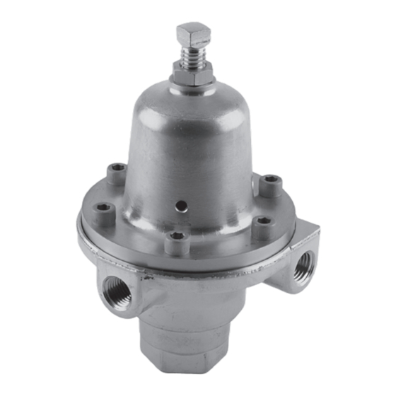
Figure 1. Type 1301F High-Pressure Regulator
Advertisement
Table of Contents

Related Manuals for Fisher 1301F


Summary of Contents for Fisher 1301F
- Page 1 Scope of the Manual such as air, gas, water, and other liquids. The Type 1301F can handle outlet pressures from 10 to This Instruction Manual provides instructions for 225 psig (0,69 to 15,5 bar) in three ranges and the...
- Page 2 Water: 1000 psig (69,0 bar) 5/64-inch (2,0 mm) Other Liquids: 2000 psig (138 bar) Spring Case Vents Outlet Pressure Ranges Type 1301F Brass Spring Case: Four 5/32-inch See Table 1 (4,0 mm) holes Maximum Emergency Outlet Pressure Type 1301F Stainless Steel Spring Case:...
- Page 3 ATMOSPHERIC PRESSURE VALVE SPRING BOTTOM CaP M1015 inLET PRESSuRE OuTLET PRESSuRE aTMOSPHERiC PRESSuRE INLET PRESSURE Figure 2. Type 1301F Operational Schematic OUTLET PRESSURE ATMOSPHERIC PRESSURE Table 1. Outlet Pressure Ranges OuTLET PRESSuRE SPRing WiRE DiaMETER, SPRing FREE LEngTH, TYPE SPRing COLOR...
- Page 4 Figures 3 and 4) clockwise to increase the set pressure or counterclockwise to decrease the set The optional brass spring case of the Type 1301F pressure. Monitor pressure with gauges during regulator has one 1/4 NPT internal connection.
- Page 5 Key numbers screws (key 17). referenced are shown in Figure 3 for the Type 1301F regulator and in Figure 4 for the Type 1301G regulator 3. The valve disk assembly (key 6) has two valve unless otherwise indicated.
- Page 6 Types 1301F and 1301G CD3923_F Figure 3. Type 1301F High-Pressure Regulator Assembly CN7095_C Figure 4. Type 1301G High-Pressure Regulator Assembly...
- Page 7 Types 1301F and 1301G Parts List note Parts marked naCE in this parts list are intended for corrosion-resistant service as detailed in the naCE international Standards MR0175/iSO 15156 and/or MR0103. Description Part number Parts Kits (Includes keys 5, 6, 7, 12, 13, and 14) Stainless steel kits include Fluorocarbon (FKM) gaskets.
- Page 8 For further information visit www.emersonprocess.com/regulators The Emerson logo is a trademark and service mark of Emerson Electric Co. All other marks are the property of their prospective owners. Fisher is a mark owned by Fisher Controls, Inc., a business of Emerson Process Management.
Need help?
Do you have a question about the 1301F and is the answer not in the manual?
Questions and answers