Advertisement
Quick Links
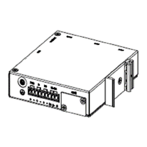
M352-5G Industrial Cellular Router
Quick Installation Guide
Install the SIM Card
STEP 1: Before inserting or removing the SIM card, ensure that the
power has been turned off, or the power connector has been
removed from the M352-5G Cellular Router.
STEP 2: Using a screwdriver to remove the metal protective cover first,
insert the SIM card into the card slot. The cut-off edge of the SIM
card on the SIM slot is to the left.
STEP 3: Push the SIM card and lightly press it to lock into the slot.
STEP 4: Remove the SIM card, lightly press it and it will pop out of the
slot.
NOTE:
Please use the industrial SIM card operating from -40°C to +105°C to ensure
proper cellular router operation.
SIM loose contacts: adding a layer of tape behind the SIM might increase
contact pressure for better attachment.
LED Indicators
The following table explains the LED indicators on the front panel.
LED
Off
SYS
Power down
Power up
SIM
Not working
Connected
Signal
No signal
High signal
Reset Button
Function
Reset
Press the button for 1 second.
Reset to default setting
Press the button for more than 5 seconds.
Connecting I/O Ports
There are four terminals on the terminal block with two terminals used
for digital input and two terminals used for digital output.
Pin
DI +
DI -
DO +
DO -
DI: Low (+0 to +3V) / High (+8 to +40V)
DO: Open Collect (maximum 30V/300mA)
Version: 1.00
On
Slow
Fast
N/A
N/A
Connecting
Error
Medium
Low
signal
signal
Operation
Description
Digital Input
Digital Output
LED Indicators of Ethernet Port
There are two LED indicators for each of the two LAN ports and one
WAN port.
LED
1G
LINK
RS-485 pinouts
Heartbeat
N/A
Connecting the Power Supply
Reading
Powering the M352-5G Cellular Router is by either a terminal block or a
DC jack.
N/A
One DC Jack is on the front panel.
The power input voltage is 12 VDC.
Antenna Installation
Tow SMA connectors placed on the right panel are for connecting to
external 5G antennas.
ANT1 and ANT2: for 5G/4G Transmit and Receive.
ANT1
-1-
Blinking
On
N/A
1000Mbps
Data Transmitting
LINK UP
Description
Pin
D +
Serial Port, Data+ (A) wire
D -
Serial Port, Data- (B) wire
G
Signal Ground
One terminal block is on the front panel.
The power input voltage range is 10~ 26 VDC.
ANT2
Off
10/100Mbps
LINK DOWN
P/N: 604040000090
Advertisement

Related Manuals for Proscend M352-5G


Summary of Contents for Proscend M352-5G
- Page 1 Power down Power up Connecting the Power Supply Not working Connected Connecting Error Reading Powering the M352-5G Cellular Router is by either a terminal block or a DC jack. Medium Signal No signal High signal signal signal One terminal block is on the front panel.
- Page 2 NOTE STEP 2: Hook the unit onto the DIN-rail. Please scan below QR Code to download online resources. Download link: https://www.proscend.com/en/product/M352.html STEP 3: Push the bottom of the unit towards the DIN-rail until it locks in place. M352 Wall Mounting STEP 1: At the bottom side of the device, use two screws to install each bracket.
Need help?
Do you have a question about the M352-5G and is the answer not in the manual?
Questions and answers