Advertisement
Quick Links
M351-5G Industrial Cellular Router
Quick Installation Guide
Install the SIM Card
STEP 1: Before inserting or removing the SIM cards, ensure that the
power has been turned off, or the power connector has been
removed from the M351-5G Cellular Router.
STEP 2: Using a screwdriver to remove the metal protective cover first,
insert the SIM cards into the card slots. The cut-off edge of the
SIM1 card (SIM 2) is to the left (right).
STEP 3: Push the SIM cards and lightly press them to lock into the slot.
STEP 4: Remove the SIM cards, lightly press them and they will pop out
of the slot.
NOTE:
Please use the industrial SIM cards operating from -40°C to +105°C to ensure
proper cellular router operation.
The USB port for the future reserve.
SIM loose contacts: adding a layer of tape behind the SIM might increase
contact pressure for better attachment.
LED Indicators
The following table explains the LED indicators on the front panel.
LED
Off
SYS
Power down
FN
Not working
SIM1
Not working
SIM2
Not working
Signal
No signal
Reset Button
Function
Reset
Reset to default setting
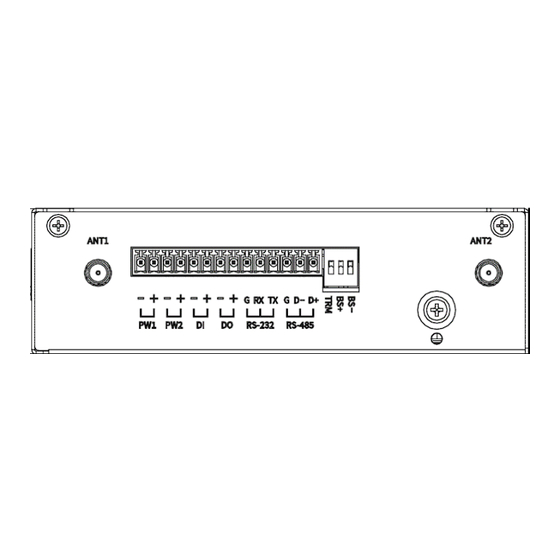
Connecting I/O Ports
There are four terminals on the terminal block, two for digital input and
two for digital output.
Pin
Description
DI +
Digital Input
DI -
DO +
Digital Output
NOTE:
DO -
*
"
"
Applicable for Wi-Fi edition only
On
Slow
Fast
Power up
N/A
N/A
Internet
N/A
N/A
connected
Connected
Connecting
Error
Connected
Connecting
Error
Medium
Low
High signal
signal
signal
Operation
Press the button for 1 second.
Press the button for more than 5 seconds.
DI: Low (+0 to +3V)/High (+8 to +40V)
DO: Open Collect (maximum 30V/300mA)
LED Indicators of Ethernet Port
There are two LED indicators for each of the four LAN ports and one
Version: 1.01
WAN port.
.
LED
1000M
LINK
Data Transmitting
RS-232 and RS-485 pinouts
RS-232
Pin
TX
Transmit Data
RX
Receive Data
Heartbeat
G
Signal Ground
N/A
RS-485
N/A
Pin
Reading
D +
Serial Port, Data+ (A) wire
D -
Serial Port, Data- (B) wire
Reading
G
Signal Ground
N/A
DIP Switch
NOTE:
(D+), (D−) stands for RS-485 pinouts.
BS−, BS+ must be in the same ON/OFF position.
-1-
Blinking
On
N/A
1000Mbps
LINK UP
Signal
Direction
Output
Input
-
Description
DIP
Mode
ON
Switch
1
BS−
Enabled (D−) 1K ohm Pull Low
2
BS+
Enabled (D+) 1K ohm Pull High
Enabled 120-ohm Termination
3
TRM
between (D+) and (D−)
Off
10/100Mbps
LINK DOWN
OFF
Disabled (D−) Pull Low
Disabled (D+) Pull High
Disabled Termination
P/N: 604040000089
Advertisement

Related Manuals for Proscend M351-5G


Summary of Contents for Proscend M351-5G
- Page 1 STEP 1: Before inserting or removing the SIM cards, ensure that the power has been turned off, or the power connector has been removed from the M351-5G Cellular Router. STEP 2: Using a screwdriver to remove the metal protective cover first, insert the SIM cards into the card slots.
- Page 2 Connecting the Power Supply Wall Mounting Powering the M351-5G Cellular Router is by either a terminal block or a STEP 1: Use two screws to install each bracket at the bottom of the DC jack. device. +, - pins of the terminal block (PW1, PW2) on the NOTE: ...
Need help?
Do you have a question about the M351-5G and is the answer not in the manual?
Questions and answers