Advertisement
Quick Links
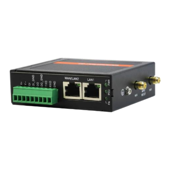
M330 Series Industrial Cellular Router
Quick Installation Guide
Install the SIM Card
STEP 1: Before inserting or removing the SIM card, ensure that the power
has been turned off, or the power connector has been removed
from the M330 Cellular Router.
STEP 2: Using a screwdriver to remove the metal protective cover first,
insert the SIM card into the card slot. The cut-off edge of the SIM
card on SIM slot is to the left.
STEP 3: Push the SIM card and lightly press it to lock into the slot.
STEP 4: Remove the SIM card, lightly press it and it will pop out of the slot.
NOTE:
Please use the industrial SIM card operating from -40°C to +105°C to ensure
proper cellular router operation.
LED Indicators
The following table explains the LED indicators on the front panel.
LED
Off
On
VPN
FN
N/A
connected
No
RSSI
High signal
signal
Power
Power
PWR
down
up
WPS and Reset Button
Function
WPS Processing
Press the button less than 5 seconds.
Reset
Press the button for 5-10 seconds.
Reset to default setting
Press the button for more than 10 seconds.
Connecting I/O Ports
There are four terminals on the terminal block with two terminals used
for digital input and two terminals used for digital output.
DI_GND
DO_GND
DI: Low (+0 to +5V) / High (+8 to +40V)
DO: Open Collect (maximum 30V/300mA)
DI: Low (+0 to +3V) / High (+8 to +40V)
Version: 1.00
Slow
Fast
Heartbeat
Internet
Booting
connected
Connected
Medium
Low
signal
signal
Processing
N/A
N/A
Operation
Pin
Description
DI
Digital Input
DO
Digital Output
LED Indicators of Ethernet Port
There is one LED indicator for LAN port and WAN port.
LED
Green
(Link / ACT)
RS-232 and RS-485 pinouts
NOTE:
RS-232 and RS-485 share the signal pins "TXD(D+)", "RXD(D-)" and common ground
pin "GND".
RS-232 (Applicable for M330-W)
Pin
TXD
Transmit Data
RXD
Receive Data
Wi-Fi
GND
Signal Ground
WPS
RS-485 (Applicable for M330-W5)
N/A
Pin
D +
Serial Port, Data+ (A) wire
D -
Serial Port, Data- (B) wire
GND
Signal Ground
Connecting the Power Supply
Powering the M330 Cellular Router is by either terminal block or a DC jack.
-1-
Blinking
Data Transmitting
LINK UP
Signal
Direction
Output
Input
-
Description
V+, V- pints of the terminal block on the front panel.
The power input voltage range is 8 ~48VDC.
One DC Jack is on the right panel.
The power input voltage is 12 VDC.
On
Off
LINK DOWN
P/N: 604040000083
Advertisement

Related Manuals for Proscend M330 Series


Summary of Contents for Proscend M330 Series
- Page 1 M330 Series Industrial Cellular Router LED Indicators of Ethernet Port Quick Installation Guide There is one LED indicator for LAN port and WAN port. Version: 1.00 Install the SIM Card STEP 1: Before inserting or removing the SIM card, ensure that the power has been turned off, or the power connector has been removed from the M330 Cellular Router.
- Page 2 Two RP-SMA connectors placed on the right panel are for connecting to Please scan below QR Code to download online resources. external Wi-Fi antennas. Download link: https://www.proscend.com/en/product/M330.html M330 DIN-rail and Wall Mounting Din-rail STEP 1: Use the screws to install the DIN-rail kit to attach at the rear side of the device.
Need help?
Do you have a question about the M330 Series and is the answer not in the manual?
Questions and answers