Table of Contents Introduction ........................6 Features ........................6 Specifications ......................7 Mechanical Dimensions ....................8 Ordering Information ....................10 Hardware Installation
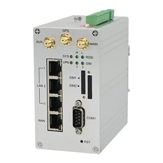
 ...................... 10 LED Indicators ......................10 Ethernet Port ......................11 Serial Port COM1 (Console-RS232) ................12 Install the SIM Card ....................13 Reset Button ......................
Page 3
Configuration > WAN ...................... 41 WAN > Priority ......................41 WAN > Ethernet ......................42 6.2.1 WAN Ethernet Configuration .................. 42 6.2.2 Ethernet Ping Health ..................... 45 WAN > IPv6 DNS ...................... 47 Configuration > LTE ......................48 LTE > LTE Config ...................... 48 7.1.1 LTE Configuration ....................
Introduction Industrial 4G LTE Cellular Router series are highly reliable and secure wireless communications gateway designed for enabling mission-critical applications and enhancing machine-to-machine connectivity for Industrial Internet of Things (IIoT). Features Highly reliable and secure for mission-critical cellular communications ...
Wireless Connectivity: 2 x SIM Card Slots Two SIM for failover/ roaming over/ back up 1 x LAN 10/100 Mbps Ethernet port (M300/M300-G) Two SIM data usage control 3 x LAN 10/100 Mbps Ethernet ports (M301/M301- ...
Mechanical Dimensions M300 model: 1 x WAN, 1 x LAN, 2 x RS232, 1 x RS485, 2 x DI, 1 x DO, 2 x SIM Card Slots, -20 ~ +70°C (2) M301 model: 1 x WAN, 3 x LANs, 2 x RS232, 1 x RS485, 2 x DI, 1 x DO, 2 x SIM Card Slots, -20 ~ +70°C...
Page 9
M301-G / M301-TG model: 1 x WAN, 3 x LANs, 1 x GPS, 2 x RS232, 1 x RS485, 2 x DI, 1 x DO, 2 x SIM Card Slots, -20 ~ +70°C (M301-G), -40 ~ +75°C (M301-TG) M301-TPG model: 1 x WAN with IEEE 802.3at/af PoE PD, 3 x LANs, 2 x RS232, 1 x RS485, 2 x DI, 1 x DO, 2 x SIM Card Slots, 1 x GPS, -40 ~ +75°C M301-GW model:...
Model Name Description Industrial 4G LTE Cellular Router M300 ( 1 x WAN, 1 x LAN, 2 x RS232, 1 x RS485, 2 x DI, 1 x DO, 2 x SIM Card Slots, -20 ~ +70°C ) Industrial 4G LTE Cellular Router...
Ethernet Port (1) 10/100 Mbps Ethernet LAN/WAN (M300/M300-G model) The LAN and WAN interface are standard RJ45 connectors. Description Function WAN TX+ 10/100 Mbps WAN, TX+ Pin WAN TX- 10/100 Mbps WAN, TX- Pin WAN RX+ 10/100 Mbps WAN, RX+ Pin...
(3) 10/100 Mbps Ethernet LAN1~LAN3/WAN (M301-TPG model) The Ethernet LAN1~3 interfaces are standard RJ45 connectors. The WAN interface is a standard RJ45 connector with IEEE 802.3at/af PoE PD. (4) LED Indicator of Ethernet Port Each Ethernet port has two LED indicators. The Green LED indicates Link/ACT, and the Yellow LED indicates Speed.
Install the SIM Card SIM1/SIM2 Card Drawers and Eject Buttons Insert and Remove SIM1/SIM2 Card (1) Before inserting or removing the SIM card, ensure that the power has been turned off and the power connector has been removed from Cellular Router. (2) Press the button with a paper clip or suitable tool to eject the SIM card from the drawer.
Reset Button Reset button allows you to reboot the unit or restore to factory default setting. Function Operation Reboot Press the button for 1 second Restore to factory default setting Press the button for 5 seconds Note: Press the Reset button and count the time around 5 seconds. The LED Indicators will be blinking to show you have activated the setting successfully.
Grounding the Router To prevent the noise and surge effect, please connect the router to the site ground wire by the ground screw before turning on the router. Pin Assignments DI1/DI2 / Alarm Contacts / COM2 (RS-232) / COM3 (RS-485) INDUSTRIAL 4G LTE CELLULAR ROUTER - UM V1.1.8...
Connecting I/O Ports (1) Digital Input DI1 & DI2 The unit has four terminals on the terminal block for the Digital inputs. Description DI1_I1 Digital INPUT 1 DI1_COM DI2_I2 Digital INPUT 2 DI2_COM INPUT : +10 to +30V for state "1" (Q1 On) ...
Serial Port COM2 (RS-232) The serial port COM2 is a RS-232 interface. Description COM2 Serial Port, RXD Signal (INPUT) COM2 Serial Port, TXD Signal (OUTPUT) COM2 Serial Port, Signal Ground(※) ※ Both connectors (RS-232 and RS-485) have a common ground connection. Serial Port COM3 (RS-485) The serial port COM3 is a RS-485 interface.
DIP Switch A built-in 120 ohm terminal resistor can be activated by DIP switch. Pull high or Pull low resistor adjustments are also available. It improves the communication on RS-485 networks for specific application. Switch 1 and 2 set the pull high/low resistor Switch 3 enables or disables the termination resistor Pull High (510 ohm) / SW 1 (Pull Low)
Configuration via Web Browser Access the Web Configurator The web configuration is an HTML-based management interface for quick and easy set up of the cellular router. Monitoring of the status, configuration and administration of the router can be done via the Web interface. After properly connecting the hardware of cellular router as previously explained.
Navigate the Web Configurator The main screen is divided into three parts as below. A -Title Bar, B-Navigation Panel and C -Main Window. A : Title Bar The title bar provides some useful instructions that appear the situation of router. Title Bar Item Description...
B : Navigation Panel-Main Menu and Sub Menu The menu items are divided into main and sub menu to configure the settings and get the status of connectivity on the navigation panel. C : Main Window This section shows the information or setting fields from main menu and sub menu. Status When you enter the web browser in the beginning and have not log in, the first item of main menu shows your status that you are a guest.
Page 22
INDUSTRIAL 4G LTE CELLULAR ROUTER - UM V1.1.8...
Page 23
Status > DO Item Description Attribute Alarm OFF Alarm configured to be disabled. Alarm ON Alarm configured to be enabled. Alarm PULSE Alarm configured to be enabled and DO in pulse mode. Force ON DO is force ON and in always mode by SMS/HTTPS. Force OFF DO is force OFF by SMS/HTTPS.
Page 24
Status > LAN Ethernet Item Description Attribute IPv4 Address Ethernet LAN is assigned IPv4 Address. IPv4 Mask Ethernet LAN is assigned IPv4 Mask. IPv6 Address Ethernet LAN is assigned IPv6 Address. IPv6 Conn Time IPv6 Connected Time. Status > WiFi Item Description Attribute...
Status > GPS For those GPS enabled router, you can see Location on the right-top banner of web interface when connecting your GPS function. After clicking Google Maps banner, a map will automatically display the current information of map according to location of router. Configuration >...
System > Time and Date This section allows you to set up the time and date of router and NTP server. There are two modes at Time and Date Setup, including Get from Time Server and Manual. The default mode is Get from Time Server.
Page 27
II. Manual Set up the information of time and date, including year, month, date, and hour, minute, and second. Set up your local time zone. Click Apply to submit your configuration changes. III. Time Zone Setup Set up Daylight Savings as On. ...
Page 28
System > Time Zone Setup > Daylight Savings Item Description Turn on/off the Daylight Savings feature. Select from Off or On. Daylight Saving The default is Off. The forward/backward minutes when enter/leave Daylight Ahead of standard time Savings duration. Default is 60 minus. Time to enter Daylight Savings duration.
IV. Time Server The Time server feature allows user to set a time server for LAN side client to get the time through NTP/SNTP protocol. System > Time Server Item Description Server mode Turn on/off the time server. Server port The UDP port listened by time server.
Page 30
(3) The console is the command-line interface (CLI) management option for cellular router. You can assign the COM port to be a management port by this option. We suggest to enable at least 1 COM port as your console port and the default console Note: port is COM 1.
Select from 1 bit or 2 bit. Stop Select from none, Xon/Xoff or hardware. Flow Control Virtual COM Select from Disable, Server or Client. Mode Select from TCP or UDP. Protocol The host address is only available on client mode. Specify what the domain name or IP address (IPv4 or IPv6) to be Host Address connected.
5.3.2 Logging > Log This section displays all data status. (1) You can choose Filter function to quickly search for your data. (2) When you click Clear, all of the data that displays on the interface will be totally cleared without any backup.
System > Alarm This section allows you to configure the alarm. Note: (1) If you select SMS in Alarm input/output, you need to add the trust phone number into Contracts/ On Duty. (2) If you select SNMP trap in Alarm output, you need to set up SNMP trap configuration from Service SNMP.
System > Alarm Item Description Turn on/off the Alarm configuration. Select from Disable or Enable. The Mode default is Enable. Select from SMS, DI 1, DI 2, VPN disconnect and WAN disconnect as input to trigger alarm. SMS: It means on duty team members on Contacts / On Duty can ...
Page 35
You can click button to edit or delete the group. INDUSTRIAL 4G LTE CELLULAR ROUTER - UM V1.1.8...
5.4.2 Alarm > Contacts > Add User Select your naming group and click + Add User button to add your user’s information, including Name, Phone and E-mail. After filling in your information for each row, chose your naming group and click ...
You can click button to edit the user’s information or click the check box and to delete the user. 5.4.3 Alarm > Duty Schedule Select Duty Schedule to edit the schedule of the on duty group. System > Ethernet This section allows you to configure the Ethernet.
Page 38
For one LAN port (M300/M300-G/) For three LAN ports (M301/M301-G/M301-TG/M301-TPG/M301-GW) INDUSTRIAL 4G LTE CELLULAR ROUTER - UM V1.1.8...
System > Ethernet Ports Item Description Ethernet Ports Status Show the connectivity status of LAN and WAN. Select from Auto, 100M Full, 100M Half, 10M Full, 10M Half Ethernet Ports Configurations and Disable. MTU is the Maximum Transmission Unit that can be sent WAN Ethernet over the WAN Ethernet interface.
For Online type, the information shows IP address and MAC address when the client is online. System > Client List Item Description DHCP Client: List all clients’ information when it is via DHCP. List Type Online: List the information when it is online. ...
Configuration > WAN This section allows you to configure WAN, including Priority, Ethernet and IPv6 DNS. WAN > Priority You can set up the priority of WAN. WAN > Priority Item Description ETH First: WAN Ethernet is first priority and the second priority is LTE. ...
WAN > Ethernet 6.2.1 WAN Ethernet Configuration This section provides three options, including DHCP Client, PPPoE Client and Static IPv4. The default is DHCP Client. WAN > Ethernet Item Description There are three options to obtain the IP of WAN Ethernet. DHCP Client: DHCP server-assigned IP address, netmask, ...
Page 43
When selecting “DHCP Client”, you can set up DNS Server Configuration. For IPv4 DNS Server, it provides three options to set up and each option has provided with “From ISP”, “User Defined” and “None” to configure. WAN > Ethernet > DHCP Client Item Description Each setting DNS Server has three options, including From ISP,...
Page 44
When you select Static IPv4, the interface shows the information of configuration, including IP Address, IP Mask and Gateway Address. WAN > Ethernet > Static IPv4 Item Description Static IPv4 Configuration IP Address Fill in the IP Address. IP Mask Fill in the IP Mask.
6.2.2 Ethernet Ping Health If you configure “WAN Priority” to “Auto” mode, the system would choose the cost effective connection first such as Ethernet. However, in case the Ethernet connection exist but it is unable to access internet; you can enable “Ethernet Ping Health” and the system would switch to LTE connection and switch back whenever Ethernet is able to access internet again.
Page 46
In addition, you can check which WAN is actually using from “Status” page. The interface will be shown check mark (✓ symbol) on the connection title. For IPv6 address, the status will be displayed on LAN Etherent Interface when IPv6 is using as WAN connection. INDUSTRIAL 4G LTE CELLULAR ROUTER - UM V1.1.8...
WAN > IPv6 DNS This section allows you to set up IPv6 DNS Server Configuration. For IPv6 DNS Server, it provides three options to set up and each option has provided with “From ISP”, “User Defined” and “None” to configure. WAN >...
Configuration > LTE This section allows you to configure LTE Config, GPS Config, Dual SIM, Usage Display, SMS, Engineer Info, and DNS. LTE > LTE Config 7.1.1 LTE Configuration You can set up the LTE Configuration and LTE Ping Health. INDUSTRIAL 4G LTE CELLULAR ROUTER - UM V1.1.8...
LTE > LTE Config Item Description Auto: Automatically connect the possible band. 4G Only: Connect to 4G network only. LTE Config 3G Only: Connect to 3G network only. 2G Only: Connect to 2G network only. MTU is the Maximum Transmission Unit that can be sent over the LTE interface.
IPv4 Host 2 Input the address of IPv4 Host 2. IPv6 Host 1 Input the address of IPv6 Host 1. IPv6 Host 2 Input the address of IPv6 Host 2. Hint Show the usage descriptions. LTE > GPS This section shows the status of GPS and allows you to set up GPS Configuration and connect RS232 from the used router to have more detailed information for your specific purpose.
Page 51
You have to select RS232 item and the interface shows the options of COM Port. Note: You can download software from internet and activate the GPS Configuration to display what information you need from your software. LTE > GPS Config Item Description Report to...
LTE > Dual SIM This section allows you to understand the status of connectivity for Dual SIM, SIM1 and SIM2. The Used SIM item has three options and the default is on Dual SIM when first connection. The Connect Retry Number field can set up the re-connecting time if your one of the SIM cards on Dual SIM mode can’t connect successfully.
Page 53
If you have selected either SIM1 or SIM2 for the Used SIM to connect, the Roaming Switch and Connect Retry Number would not to be shown in the interface. You can set up the SIM cards, SIM1 Configurations or SIM2 Configurations. SIM PIN: If you have configured SIM PIN code into SIM card, please type SIM PIN code in ...
Page 54
Change SIM PIN:If you want to change SIM PIN code, you can click Change button and type old SIM PIN code and new SIM PIN code. Please aware not to exceed the retry number (PIN remaining number and PUN remaining number). Note: The interface will be shown the tick symbol at the same time when each SIM Card has been connected.
Page 55
LTE > Dual SIM Item Description Connect Policy Current SIM Card Display which SIM slot is using. Connect: After manually disconnect, user can only click Connect button to get connection or reboot the device to make it automatically connect. Status of SIM Card Connectivity Disconnect: If there is one SIM slot get connection, the Disconnect...
Page 56
The password can be input by user or the system will search from Password internal database if the password is blank. Confirm Password Double confirm password. Configure Authentication mode with three modes, including NONE, Auth PAP, and CHAP. If Auth mode is not None, most servers require (NONE/PAP/CHAP) username and password above.
LTE > Usage Display This section shows the status of current SIM card, operator, IMSI and the charts for Real Time, Hourly, Daily, Weekly, and Monthly. (1) Real-Time Usage: It displays accumulated real-time Download/Upload/Total MB for 10 seconds period. INDUSTRIAL 4G LTE CELLULAR ROUTER - UM V1.1.8...
Page 58
(2) Hourly Usage: It displays Download/Upload/Total MB per hour in one day for current using SIM card and the view window size is 24 hours. INDUSTRIAL 4G LTE CELLULAR ROUTER - UM V1.1.8...
Page 59
(3) Daily Usage: It displays Download/Upload/Total MB per day in one month for current using SIM card and the view window size is 31 days. INDUSTRIAL 4G LTE CELLULAR ROUTER - UM V1.1.8...
Page 60
(4) Weekly Usage: It displays Download/Upload/Total MB per day in one week for current using SIM card and the view window size is 7 days. INDUSTRIAL 4G LTE CELLULAR ROUTER - UM V1.1.8...
Page 61
(5) Monthly Usage: It displays Download/Upload/Total MB per month in one year for current using SIM card and the view window size is 12 months. INDUSTRIAL 4G LTE CELLULAR ROUTER - UM V1.1.8...
LTE > SMS This section provides two settings, one is SMS Action and the other is View SMS. (1) When enabling SMS Action, it allows trust phone number which in Contacts/On Duty list by sending key words SMS to trigger device setting/action/query status. INDUSTRIAL 4G LTE CELLULAR ROUTER - UM V1.1.8...
Page 63
(2) View SMS allows you to review the information of SMS that you have received, including the state, phone and date and time. You can click view button to review all messages, button to clear all messages, and button to reload all messages. INDUSTRIAL 4G LTE CELLULAR ROUTER - UM V1.1.8...
LTE > Serving Cell This section displays all parameters, including the following items: LTE > Serving Cell Item Description Reference Signal Received Power. RSRP RSRQ Reference Signal Received Quality. SINR Loarithmic value of SINR. RSCP The Received Signal Code Power Level of the cell that was scanned. ECIO Carrier to noise ratio in dB = measured Ec/lo value in dB.
LTE > Lock PCIs This section allows you to search neighbors, lock/unlock PCIs and save locked PCIs. 7.7.1 Neighbors LTE > Lock PCIs > Neighbors Item Description Search Search Neighbors from the Air for further action. Lock Select multiple PCIs (Physical Cell ID) from Neighbor List to lock. Unlock Unlock all.
LTE > Lock Bands Please check Hint for module support bands and then select your desired multiple bands to lock for use. LTE > DNS This section allows you to setup LTE specific DNS setting. INDUSTRIAL 4G LTE CELLULAR ROUTER - UM V1.1.8...
LTE > DNS Item Description 1. Each setting DNS Server has three options, including From ISP, User Defined and None. IPv4 DNS Server #1 2. When you select From ISP, the IPv4 DNS server IP is obtained IPv4 DNS Server #2 from ISP.
Configuration > LAN This section allows you to configure LAN IPv4, LAN IPv6, VLAN and Subnet. LAN > IPv4 Set up your IP Address and IP Mask. Also, fill in the information of DHCP Server Configuration. LAN > IPv4 Item Description IP Address:192.168.1.1 ...
LAN > IPv6 Select your type of IPv6, which shows Delegate Prefix from WAN or Static, and then set up DHCP Server Configuration, including Address Assign, DNS Assign and DNS Server. LAN > IPv6 Item Description Delegate Prefix from WAN ...
Page 71
When VLAN Mode is set to Tag Base, the VLAN setting window will appear as shown below. For each row, the settings can be enabled or disabled by checkbox and select the Subnet and the VLAN ID (VID). The Subnet sets up the IP address and IP mask for the router, so this router can communicate with the third party by this IP address and IP mask on this VLAN.
Page 72
Type 2: For 3-port LANs, the VLAN Mode allows you to select Off, Tag Base (802.1p) or Port Base. When VLAN Mode is set to Tag Base, the VLAN setting window will appear as shown below. The VLAN Isolation function allows administrator to separate the different Subnet (VLAN). When it is on, the different Subnet (VLAN) user cannot communication each other.
Page 73
which is a gate allows those ports to access internet or the router. The PVID and Tag Mode are for LAN1, LAN2 and LAN3 ports. The PVID provides the untagged devices to communicate with third-party devices. (Note: The untagged devices mean not to support 802.1p VLANs.) The Tag Mode can be Trunk or Access.
LAN > VLAN (3-port LANs) > Port Base Item Description Mode The VLAN mode is Off, Tag Base (802.1p VLAN) or Port Base. Enable The assigned row of setting is enabled. The port is shown to assign the port to a VLAN which the device is Port connected from LAN 1, LAN2, LAN3 and Router.
IP Routing This section allows you to configure the Static Route, RIP, OSPF, and BGP. IP Routing > Static Route This section allows you to configure the Static Route. A static route is a pre-determined path that network information must follow to reach a specific host or network. IP Routing >...
Page 76
Name Set up each name for your running host or network. Destination Fill in the destination of a specific subnet or IP from network. Gateway Fill in the gateway address of your router. Interface Select the interface from LAN or Ethernet. Note: The destination field is required to fill in.
The status tab shows the information from the settings of static route. IP Routing > Static Route > Status Item Description Mode The setting is open for full network. Select from Off or On. Status Destination Show the status of destination from the setting section. Gateway Show the status of gateway from the setting section.
Page 78
IP Routing > RIP > General Item Description General Mode Select from Off or On to open or close RIP function. Redistribute local routes Select from Off or On to open or close redistribute local routes. Redistribute connected Select from Off or On to open or close redistribute connected routes routes.
IP Routing > RIP > Interfaces Item Description Interfaces Mode Select from Off or On to use or not to use the RIP function in the interface. Interface Select from eth1 (WAN Ethernet) or LAN. Select from none or md5 to approve authentication. Authentication Note: Please offer Key and Key ID when you select md5 to use HMAC-MD5.
Page 80
On: Redistribute connected routes to networks which are directly connected to the device. Off: Not redistribute RIP routes learned via the RIP routing protocol. Redistribute RIP routes On: Redistribute RIP routes learned via the RIP routing protocol. Off: Not redistribute BGP routes learned via the RIP routing ...
Page 81
IP Routing > OSPF > Interfaces Item Description Mode Select from Off or On to use or not to use the OSPF function in the interface. Interface Select from eth1 (WAN Ethernet) or LAN. Select from none or md5 to approve authentication. Authentication Note: Please offer Key and Key ID when you select md5 to use HMAC-MD5.
IP Routing > OSPF > Networks Item Description Mode Select from Off or On to enable the network setting. Prefix Set Prefix of the network Prefix Length Set Length of the prefix Area Routing area to which this interface belongs (0-65535, 0 means backbone) IP Routing >...
Page 83
(2) Neighbor Configuration The neighbors sub configuration is used to configure all the BGP routers to peer with and the maximum neighbors is 16. IP Routing > BGP > Neighbors Item Description Mode Select from Off or On to enable the neighbor setting. IP Address Set IP address of the peer router.
Page 84
(3) Networks Configuration The networks sub configuration allows to add IP network prefixes that shall be distributed via BGP in addition to the networks that are redistributed from other sources as defined on the general sub configuration and the maximum neighbors is 16. IP Routing >...
Configuration > VPN This section allows you to configure Open VPN, IPsec, GRE, PPTP Server, and L2TP. VPN > Open VPN 11.1.1 Open VPN Common Setting (1) This section allows you to configure the Open VPN parameters. The default mode is Disable. Click button to edit Open VPN Connection.
Page 86
(2) From Setting tab, you can set up the connection of Open VPN. (3) From Log tab, the interface will be shown the status of connection to make you follow the suitation whenever is successful or fail connection. VPN > Open VPN > Setting Item Description Mode...
Page 87
Roadwarrior (default) VPN Type Bridging: Bridging the VPN tunnel and LAN/VLAN Status Display the status of Open VPN. TLS Mode Select from Disable or Enable for data security. The default is Disable. Cipher The Open VPN format of data transmission. IPv6 Mode Select from Disable or Enable.
11.1.2 Open VPN Client Setting Select option “Client” from VPN Mode, and this section allows you configure the Open VPN client route and authentication files. The files could be imported by clicking Import button and the file should be downloaded from Open VPN server.
11.1.3 Open VPN Server Setting Select option “Server” from VPN Mode, and this section allows you to configure the server status of VPN Mode. When selecting the On option of Route Client Networks, the Open VPN server will route Note: the client traffic or not.
VPN > Open VPN > Server VPN Mode Item Description Server VPN Network The network ID for Open VPN virtual network. VPN Netmask The netmask for Open VPN virtual network. Select from Off or On. The Open VPN server will route the client Roadwarrior: traffic or not.
Page 91
VPN > Open VPN > Custom VPN Mode Item Description Mode Select from Disable or Enable. The default is Disable. VPN Mode Select from custom mode. Custom Config Import Open VPN configuration. Username Fill in the username if the imported file has already set up the username. Password Fill in the password if the imported file has already set up the password.
VPN > IPsec This section allows you to set up IPsec Tunnel. The seting has four tags, Connections, Authentication IDs, X.509 Certificates, and CA Certificates. For the IPsec connection which be authenticated by pre-shared key, it only need to setup the Connections and Authentication IDs.
Page 93
(1) IPsec Phase 1 Setting VPN > IPsec > Connections > Phrase 1 setting Item Description Mode Select from Disable or Enable. The default is Disable. Name Short name or description. Protocol Select from IKEv1 or IKEv2. The default is IKEv1. Select from Disable or Enable.
Page 94
The IP address of the router's public network interface. Local Host If this value is blank, the connection will automatically detect the correct IP address. The identification for authentication on local peer. Local ID Select from the created authentication IDs or empty. The IP address of the peer gateway's public network interface.
Note: (1) This option only work on Policy-based IPsec VPN type. (2) This option will be setup as 0.0.0.0/0 automatically on IPsec Route-based VPN. (3) This option will be omitted when the service option is L2TP. (For host-to-host connection only) The private subnet behind the peer gateway.
Page 96
VPN > IPsec > Authentication IDs Item Description The identification for authentication. It only work on PSK type. Select from PSK or RSA. The default is PSK. Type PSK: Use the pre-shared key to authenticate the connection. RSA: Use the certificate to authenticate the connection. ...
11.2.3 IPsec > X.509 Certificates This section provides the certificates setting which could be used by IPsec authentication ID. Each certificate will show the State and Subject information and provide the controlling buttons to let user import, download or edit the certificate/key files. Please apply the changes before editing the Authentication IDs settings.
Page 98
Certificate Generation There are two kinds of certificate could generated by router, one is self-signed CA, the other is X.509. To generate the self-signed CA certificate: 1. Navigate to CA Certificates tab. 2. Click the edit button to navigate the Certificate Setting page. 3.
Page 99
Certificate Setting VPN > IPsec > CA Certificates Item Description The 2-letter country code. e.g. US Country Name This option is required for certificate generation. State The state name. e.g. Some-State Location The location name. e.g. city-name The orgnization name. e.g. company-name Orgnization Name This option is required for certificate generation.
2. Click the + Add X.509 button. The list will pop up the balnk X.509 entry. 3. Click the Cert Import button. 4. Select the X.509 certificate file from browser window. 5. When the file be selected and everything all right, the state should be Cert or Key is missed.
Page 101
5. Navigate to the Connections tab. 6. Add IPsec connection (1) Edit the phase 1 setting (2) Change Mode from Disable to Enable. (3) Save the changes. (4) Edit the phase 2 setting (5) Fill up the Local Subnet and Remote Subnet. e.g.
Page 102
INDUSTRIAL 4G LTE CELLULAR ROUTER - UM V1.1.8...
Page 103
Configure Net-to-Net VPN Client 1. Change Mode from Disable to Enable. 2. Navigate to the Authentication IDs tab. 3. Add the authentication ID Keep ID as blank, Type as PSK and fill the password to Pre-shared Key field. 4. Apply the changes 5.
Page 104
INDUSTRIAL 4G LTE CELLULAR ROUTER - UM V1.1.8...
Page 105
IPsec Net-to-Net with Pre-shared Key result Server Client RSA authentication - Server Prepare the self-signed CA certificate 1. Navigate to the CA Certificates tab. 2. Edit the self-signed CA. (Skip it if the self-signed CA is generated.) (1) Fill the information of the self-signed CA (2) Country Name: CN (3) Orgnization Name: Company...
Page 106
Prepare the X.509 certificates 1. Navigate to the X.509 Certificates tab. 2. Click the add button to add the X.509 certificate 3. Edit the newly X.509 certificate for the local router. (1) Fill the information of the X.509 certificate (2) Country Name: CN (3) Orgnization Name: Company (4) Common Name: local.IPsec (5) Click the Generate Certificate button...
Page 107
INDUSTRIAL 4G LTE CELLULAR ROUTER - UM V1.1.8...
Page 108
INDUSTRIAL 4G LTE CELLULAR ROUTER - UM V1.1.8...
Page 109
Prepare the authentication IDs 1. Navigate to the Authentication IDs tab. 2. Add tow authentication IDs Keep first one's ID as blank, Type as RSA and select the C=CN, O=Company, CN=local.IPsec X.509 certificate. Keep second one's ID as blank, Type as RSA and select the C=CN, O=Company, CN=remote.IPsec X.509 certificate.
Page 110
INDUSTRIAL 4G LTE CELLULAR ROUTER - UM V1.1.8...
Page 111
RSA authentication – Client Prerequisite for VPN Client with RSA authentication 1. The self-signed CA certificate which generated by VPN server 2. The X.509 certificate and key for remote router which generated by VPN server These files could be downloaded from VPN server. The detail could reference “ How to download the certificate section ”...
Page 112
Setup the connection on VPN client 1. Change Mode from Disable to Enable. 2. Navigate to the Authentication IDs tab. 3. Add one authentication ID Keep second one's ID as blank, Type as RSA and select the C=CN, O=Company, CN=remote.IPsec X.509 certificate.
Page 113
INDUSTRIAL 4G LTE CELLULAR ROUTER - UM V1.1.8...
Page 114
IPsec Net-to-Net with RSA authentication result Server Client INDUSTRIAL 4G LTE CELLULAR ROUTER - UM V1.1.8...
11.2.6 IPsec > Hub-Spoke Topology This section explains how to set Hub-Spoke Topology and connect two (or more) gateways to a central one. This requires one connection between each spoke and the central hub (n - 1 connections for n gateways) For example, in the Hub-and-Spoke topology, we want to send the essential traffic through IPsec VPN tunnel.
Page 116
Hub configuration Hub IPsec configuration In this example, we have two spokes on the topology. Thus, the Hub needs to set two IPsec connections for each spoke. 1. Change Mode from Disable to Enable. 2. Change Type from Policy-based to Route-based. 3.
Page 117
INDUSTRIAL 4G LTE CELLULAR ROUTER - UM V1.1.8...
Page 118
INDUSTRIAL 4G LTE CELLULAR ROUTER - UM V1.1.8...
Page 119
Hub Static Route configuration IP Routing > Static Route 1. Navigate to the page 2. Add the static route for IPsec Spoke 1 connection Mode: On Destination: 192.168.100.0/24 Interface: Select the IPsec interface by connection number ...
Page 120
Spoke 1 configuration Spoke 1 IPsec configuration 1. Change Mode from Disable to Enable. 2. Change Type from Policy-based to Route-based. 3. Navigate to the Authentication IDs tab. 4. Add default pre-shared key (1) ID: (2) Type: PSK (3) Pre-shared Key: defaultpsk 5.
Page 121
INDUSTRIAL 4G LTE CELLULAR ROUTER - UM V1.1.8...
Page 122
Spoke 1 Static Route configurtation 1. Navigate to the IP Routing > Static Route page 2. Add the static route for IPsec connection Mode: On Destination: 192.168.200.0/24 Interface: Select the IPsec interface by connection number e.g. If your IPsec connection is #1 then the interface should be IPsec#1. 3.
Page 123
Spoke 2 configuration Spoke 2 IPsec configuration 1. Change Mode from Disable to Enable. 2. Change Type from Policy-based to Route-based. 3. Navigate to the Authentication IDs tab. 4. Add default pre-shared key ID: (The ID is blank.) ...
Page 124
INDUSTRIAL 4G LTE CELLULAR ROUTER - UM V1.1.8...
Page 125
Spoke 2 Static Route configurtation 1. Naviagte to the IP Routing > Static Route page 2. Add the static route for IPsec connection Mode: On Destination: 192.168.100.0/24 Interface: Select the IPsec interface by connection number e.g. If your IPsec connection is #1 then the interface should be IPsec#1. 3.
VPN > GRE This section allows you to set GRE configuration. The default mode is off. Generic Routing Encapsulation (GRE) is one of the available tunneling mechanisms which uses IP as the transport protocol and can be used for carrying many different passenger protocols. The tunnels behave as virtual point-to-point links that have two endpoints identified by the tunnel source and tunnel destination addresses at each endpoint.
VPN > PPTP Server This section provides 2 sub configurations, including General Configuration and Clients Configuration. (1) General Configuration VPN > PPTP Server > General Item Description Mode Select from Off or On to enable PPTP Server. IP addresses to be used at the local end of the tunneled PPP links Server Address between the server and the client.
Page 128
INDUSTRIAL 4G LTE CELLULAR ROUTER - UM V1.1.8...
VPN > L2TP This section allows you to set up L2TP and provides three modes for configuration, including Off, Server, and Client Mode. (1) Genernal Mode: The defualt mode is Off as shown in the following interface. (2) Server Mode: Choose the Server mode and the interface will be changed as below.
Page 130
Fill in the username and password and click the button, you can create the L2TP client and manage them under server mode. (3) Client Mode: Choose the Client mode and the interface will be changed as below. INDUSTRIAL 4G LTE CELLULAR ROUTER - UM V1.1.8...
Page 131
VPN> L2TP > Client Mode Item Description Mode Turn on/off this L2TP connection Server The L2TP server address or hostname. The authentication method for L2TP connection. Should same as L2TP Auth server's auth type. Username The username for L2TP authentication. Password The password for L2TP authentication.
Configuration > Firewall This section allows you to configurate Port Forwarding, DMZ, IP Filter, MAC Filter, URL Filter, NAT and IPS. Firewall > Port Forwarding This section allows you to set up Port Forwarding and click edit button to configure. INDUSTRIAL 4G LTE CELLULAR ROUTER - UM V1.1.8...
Firewall > Port Forwarding Item Description Turn on/off Port Forwarding to select Disable or Enable. The Mode default is Disable. Descript the name of Port Forwarding. Description Select from UDP or TCP Client which depends on the application. Protocol Fill in the beginning of source port. Source Port Begin Fill in the end of source port.
Firewall > IP Filter This section allows you to configure IP Filter. After clicking button, you can edit your IP protocol, source/port and destination/port. The default is Disable mode and Black list. INDUSTRIAL 4G LTE CELLULAR ROUTER - UM V1.1.8...
Page 135
Black List: When set as Black List, the specific IP address/port in rule will be blocked. White List: When set as White List, the specific IP address/port in rule will be accepted. Management IP Address: For White List only. Since White List will block all user communication except those has been assigned by rules, it is better to assign a specific IP address for the administrator to access the Router which is Management IP Address.
Page 136
Edit Black/White List (1) Click button to edit Black/White list. (2) The default is Disable mode as the following interface (Black/White). INDUSTRIAL 4G LTE CELLULAR ROUTER - UM V1.1.8...
Page 137
Firewall > IP Filter Item Description Mode Select from Disable or Enable. The default is Disable. Protocol Select from All, ICMP, TCP or UDP. Source IP Fill in your source IP address. Source Port Fill in your source port. Destination IP Fill in your destination IP address.
Firewall > MAC Filter This section allows you to set up MAC Filter. After clicking button, you can edit your MAC address. Service > MAC Filter Item Description Mode Select from Disable or Enable. The default is Disable. MAC Address Fill in your MAC address.
Firewall > URL Filter This section allows you to set up URL Filter. After clicking button, you can edit the type of filter and information. INDUSTRIAL 4G LTE CELLULAR ROUTER - UM V1.1.8...
Please not include “https://” or “http://” for the URL address in the Full Filter. Note: Firewall > URL Filter Item Description Mode Select from Disable or Enable. The default is Disable. Filter Select from Key or Full. The default is Key. Key / Full Fill in your Key / Full information.
Firewall > IPS This section allows you to set IPS configuration. IPS prevents the system from being attacked by the Internet. The system allows to limit the max incoming connection number from WAN per source IP address to prevent system resource exhausted. Also, the system allows to limit the max incoming connection retry number during a specific time period from WAN per source IP address to prevent too many unexpected connections retry event from causing system busy.
Configuration > Service This section allows you to configure the SNMP, TR069, Dynamic DNS, VRRP, MQTT, UPnP, SMTP, and IP Alias. Service > SNMP 13.1.1 Community This section allows you to set the SNMP configuration. INDUSTRIAL 4G LTE CELLULAR ROUTER - UM V1.1.8...
Service > SNMP > Community Item Description Mode Select from Disable or Enable to configure SNMP. Community Configure community setting with three options, including # 1, # 2 and #3. Mode Select from Disable or Enable. Name Name each community. Access Select from Read-Only or Read-Write.
13.1.3 SNMP trap configuration This section allows you to set up the SNMP trap configuration when you select the SNMP trap function from Alarm output of system for your router. With SNMP trap setting, you can know the status of remote device. Service >...
Service > TR069 This section allows you to set up TR069 client configuration. You can get information how to install TR069 Server (GenieACS Installation) from the application configuration chapter. Service > TR069 Item Description Mode Select from Disable or Enable. The default is Disable. ACS URL Fill in the URL address of ACS (Auto-Configuration Server).
Service > Dynamic DNS This section allows you to set up Dynamic DNS. Service > Dynamic DNS Item Description Turn on/off this function to select Disable or Enable. The Mode default is Disable. Service Provider Select the Service Provider of Dynamic DNS. Host Name Fill in your registered Host Name from Service Provider.
Page 147
Note: There are six options of Service Provider as below to explain the information. Service Provider dynv6.com Host Name Register hostname, e.g. tester.dynv6.net Token ID The token ID, e.g. v_ABjMMQxeAnWv5UwtuVn1QBriynzq Service Provider www.nsupdate.info Host Name Register hostname, e.g. tester.nsupdate.info Host Secret ID The Host Secret ID, e.g.
Service > VRRP This section allows you to configure VRRP. Service > VRRP Item Description Mode Select from Disable or Enable. The default is Disable. Group ID Specify which VRRP group of this router belong to (1-255). The default is 1. Enter the priority value from 1 to 254.
Service > MQTT This section makes you configure MQTT which allows the MQTT client to send the message within specific topic or channel. By default, the router does not allow anonymous to read/write the MQTT topic or channel. Thus, you need to create the account with username and password for MQTT client in the web UI.
Page 150
Take for example, the interface is shown as below. The Manage Users section will show all users that you create. Moreover, each user can use the delete button to delete it. For the ACLs control, user can specify what topic should be limited. In this case, we set up the publisher pub1 to write the critical topic.
Service > UPnP This section allows you to set up UPnP confirguration to select the mode from Disable or Enable. The default UPnP is enabled for the cellular router. Note: UPnP™ (Universal Plug and Play) is a set of protocols that allows a PC to automatically discover other UPnP devices (anything from an Internet gateway device to a light switch), retrieve an XML description of the device and its services, control the device, and subscribe to real-time event notification.
Service > IP Alias This section allows you to set IP Alias configuration. IP Alias is associating more than one IP address to a network interface. With IP Alias, one node on a network can build multiple connections with the network, each serving a different purpose. IP Alias can be used to provide multiple network addresses on a single physical interface.
Service > QoS (Quality of Service) QoS (Quality of Service) refers to a network's ability to achieve maximum bandwidth and allow minimum bandwidth. It guarantees the minimum and limit the maximum bandwidth for certain class of traffic. The QoS configuration has three parts, including ISP bandwidth, QoS and Status. ISP bandwidth allows user to configure the max bandwidth for upstream and downstream of ...
13.9.2 QoS You can select QoS tab and show a overall view for QoS configuration. At right side of window, there are three buttons. botton allows you to edit QoS Entry and configure QoS settings. button allows you to adjust priority of the QoS entry. The first QoS entry is the highest priority.
Page 155
The QoS entry configuration page has three parts for classify traffic, assign bandwidth, and group IP address bandwidth. 1. Classify traffic by following items: Service > QoS > Edit QoS Entry Item Description Mode Select from Disable or Enable QoS. Name The setting can be edited or deleted the existed entries.
Page 156
2. Assign bandwidth by following items: Min Rate / Max Rate: The unit is kilobits per second. Min Rate guarantee the minimum bandwidth and Max Rate is the limit bandwidth. 3. Assign group IP bandwidth by following items: Bandwidth divided for each IP Address: When this feature is selected, the bandwidth assigned by Min Rate / Max Rate will be divided by the number of IP addresses.
13.9.3 Status 1. Refresher Setting select the showed content of bandwidth usage by following items: Refresh rate: how long the browser will update the showed content once. Direct: show Upstream or Downstream. Show detail bandwidth for each IP address: show the group IP bandwidth usage. ...
Page 158
Step 3: Set QoS Entry #2 Step 3.1: Set Mode as Enable Step 3.2: Set Name as Internet Browse DS. Step 3.3: Select Interface LTE. Step 3.4: Select Downstream. Step 3.5: Set Port Begin/End as 443/443. ...
Page 159
Step 4: Apply Step 5: Check the internet access is ok through LTE. (Since we selected LTE interface.) Step 6: Start browse the internet from LAN PC. Step 7: Check Upstream Status. The traffic in entry “Internet Browse US” is Upstream, LAN to WAN, and send request to public Web Server with destination port number 443.
Page 160
Step 8: Check Status Downstream. The traffic in entry “ Internet Browse DS ” is Downstream, WAN to LAN, and send response from public Web Server with source port number 443. The base of percentage is ISP Bandwidth > LTE > Downstream setting. It is 1000 kbps in our example.
13.9.5 Bandwidth divided for each IP address There are ten number of IP addresses. The most left different octet is “ 11 ” in 192.168.1.11 and “ 2 ” in 192.168.1.2, so number of IP addresses is calculated by 11 minus 2 and plus one for boundary.
Configuration > Management This section provides you to manage the router, set up your administration and know about the status of current software and firmware. Also, you can back up and restore the configuration. Management > Identification This section allows you to confirm the profile of router, current software, firmware version and system uptime.
Management > Identification Item Description Model Name Show the model name of cellular router. LAN Ethernet MAC Address Show the LAN Ethernet MAC address. WAN Ethernet MAC Address Show the WAN Ethernet MAC address. Bootloader Version Show the bootloader version currently running on the device. Software Version Show the software version currently running on the device Serial Number...
Page 164
INDUSTRIAL 4G LTE CELLULAR ROUTER - UM V1.1.8...
Management > Contacts / On Duty This section allows you to create the groups, add the usersFor more detailed instruction, please navigate to System > Alarm. 14.3.1 Contacts + Add Group: Please fill out group name. + Add User: Please fill out Name/Phone/E-Mail/Groups. 14.3.2 Duty Schedule Please select duty date for every group.
Management > SSH Secure Shell (SSH) allows user to configure system via a secure channel. User can configure system from either public domain or local LAN. Management > SSH Item Description Mode Select from Disable or Enable SSH function. Server Port The port number is where SSH server works on.
Management > Web This section allows user to change the HTTP port via HTTP. As long as pressing Apply, the web daemon will restart the new configuration, and you won’t see the response at the web browser. We need a way to reply immediately and apply the configuration latter. By using fork, we can make parent process reply immediately and the child process execute the configuration.
Management > Firmware This section provides you to upgrade the firmware of router. (1) Click button to choose your current firmware version in your PC. (2) Select button to update. (3) After upgrading successfully, please reboot the router. Management > Configuration This section supports you to export or import the configuration file.
Management > Schedule Reboot The setting allows you to schedule the reboot time regularly. Schedule Type – Interval Schedule Type - Per Day Schedule Type - Per Week Schedule Type - Per Month INDUSTRIAL 4G LTE CELLULAR ROUTER - UM V1.1.8...
Configuration > Diagnosis This section allows you to diagnose Ping and Traceroute for your Host (IP address or Domain Name). Diagnosis > Ping Please assign the Host you want to ping. The result of the ping is as below. INDUSTRIAL 4G LTE CELLULAR ROUTER - UM V1.1.8...
Diagnosis > Traceroute Please assign the Host **you want to** traceroute. The result of the traceroute is as below. INDUSTRIAL 4G LTE CELLULAR ROUTER - UM V1.1.8...
Configuration Applications This section explains specific examples how to configure your applications. WAN Priority You can select from ETH First, LTE Only, ETH Only or LTE First. (1) WAN Priority > ETH First: In case both Ethernet and LTE can access Internet, the router would route network packages through Ethernet.
Page 173
(3) WAN Priority > ETH Only: In this mode, the router only routes network packages through Ethernet. (4) WAN Priority > LTE First: In case both Ethernet and LTE can access Internet, the router would route network packages through LTE. However, in case LTE is unplug or not able to access Internet (check by ping), the router would route network packages through Ethernet network.
LAN > IPv4/IPv6 Dual Stack The router supports IPv4/IPv6 dual stack by default, it means IPv4 packages route to IPv4 network and IPv6 route to IPv6 network. Since IPv6 is global IP, there is no NAT between WAN site and LAN site. One device only needs one global IPv6.
Page 175
The router automatically detects IPv6 environment and query IP. After the IP is obtained successfully, it will distribute to LAN site hosts. INDUSTRIAL 4G LTE CELLULAR ROUTER - UM V1.1.8...
MQTT Broker The cellular router provides the MQTT broker feature which allow the MQTT client sending the message within specific topic (channel). By default, the cellular router does not allow anonymous to read/write the MQTT topic (channel). Thus, you need to create the account with username and password for MQTT client in the web The Manage Users section will show all created users.
For example, we set the publisher pub2 to write the critical topic. Additionally, we also the subscribers sub1 and sub3 can read the critical topic. Thus, when pub2 is sending the message only the sub1, the sub3 can receive it. Virtual COM >...
Page 178
You can click the Edit button to configure COM2 setting. The configuration UI shows the following picture. The configuration UI provides the serial setting and the Virtual COM setting. (1) For the serial setting, you need to change the setting like baud rate to fit the connected device. (2) For the Virtual COM, you need to change the mode to Server and specify the Protocol, Port to reach the remote management feature.
Page 179
Remote Port 6000 as the following picture. INDUSTRIAL 4G LTE CELLULAR ROUTER - UM V1.1.8...
Virtual COM > Remote Alarm When the router connected with the alarm device, the alarming data from the device can be forwarded by the router to the warning center. Same as the remote management, the serial settings of connected COM port need to be configured properly. And the virtual should be opened and run as Client mode.
Virtual COM > Modbus RTU over TCP For the industrial products, the Modbus protocol is the most popular industrial control protocol. If the Modbus software/SCADA supported the Modbus RTU over TCP, the Virtual COM server feature of router could handle it. You need to configure the RS-485(COM3) like the remote management (serial settings, Virtual COM settings).
Modbus Gateway The Modbus gateway feature of router could convert the Modbus TCP to the Modbus RTU protocol and send it to the connected RS-485 device. This feature depends on the COM3 setting, you need to configure the serial setting in the System -> COM ports web UI and set up this feature in the System ->...
Page 183
(2) Alarm Output: In case of SMS is selected then only user’s phone number is in selected group and on selected working day would receive alarm SMS. In case of DO is selected, please make sure your DO is connected to your alarm device. ...
Open VPN Configuration Generic setup For Open VPN configuration, use the certificate to authenticate the VPN connection. Thus, you need to generate the required files for Open VPN server or import the required file to Open VPN client. 16.9.1 Open VPN Server Mode Open VPN server certificate generation For the Open VPN server mode, the Open VPN web UI provides the buttons to generate the required files.
And you can click the info button to show the detail for each files, or click the download button to download the file to PC. 16.9.2 Open VPN Client Mode Open VPN client certificate import For the Open VPN client mode, the Open VPN web UI provides the buttons to import the required files.
16.9.3 Open VPN Net-to-Net You can use the Open VPN VPN tunnel to make the PC1 and PC2 communicate each other. (1) Open VPN server configuration For the Open VPN server side, the basic setting is as shown in below figure. INDUSTRIAL 4G LTE CELLULAR ROUTER - UM V1.1.8...
Page 187
The VPN Network and VPN Netmask are required fields. The VPN Network should be network ID (e.g. 192.168.30.1 is invalid setting.) Note: When PC1 and PC2 communicate each other, the Route Client Networks should be enabled. And add the LAN information of Open VPN client side, in this case the #1 route will be 10.0.0.0 and 255.255.255.0 The #1 route means the routing information for User 1.
Page 188
(2) Open VPN client configuration For the Open VPN client side, the basic setting is as below figure. The Server Address is required field, which indicate the Open VPN server address which Open VPN client try to connect. And the PKCS12 Password only works when selected the pkcs #12 Certificate authentication option.
16.9.4 Open VPN 1:1 NAT For the net-to-net part, the Open VPN server LAN network and the Open VPN client LAN network are different. But some time, the LAN network will be same for both sides. When this situation occurred, the routing rules will be ambiguous that will result in the PC1 and the PC2 can't communicate each other.
For the Open VPN client side, same as server side but we fill up the Network as 192.168.11.0. The setting will make router convert the Open VPN client side LAN network from 192.168.1.0/24 to 192.168.11.0/24 when the VPN traffic is coming. 16.9.5 Open VPN with third-party server A VPN enables you to send and receive data across shared networks.
Page 191
For example, use the Japan Open VPN server which provided by http://www.vpngate.net/en/ . Firstly, download the ovpn configuration files from vpngate.net. Additionally, use the Open VPN custom import button to import it. The result is as the below figure. If the .ovpn configuration file is correct, the web UI will show Apply OK. If the third-party Open VPN server is reachable, the VPN tunnel will be established.
16.9.6 Install Open VPN Access Server on Docker Open VPN Access Server on Docker installation Open VPN Access Server is a full featured secure network tunneling VPN software solution that integrates Open VPN server capabilities, enterprise management capabilities, simplified Open VPN Connect UI, and Open VPN Client software packages that accommodate Windows, MAC, Linux, Android, and iOS environments.
Page 193
Install Docker CE sudo apt-get update sudo apt-get install docker-ce Install Open VPN Access Server by docker image Reference: https://hub.docker.com/r/linuxserver/Open VPN-as/ sudo mkdir -p /Open VPN-as sudo docker create --name=Open VPN-as \ -v /Open VPN-as:/config \ -e TZ="Asia/Taipei" \ -e INTERFACE=enp3s0 \ --net=host --privileged linuxserver/Open VPN-as sudo docker start Open VPN-as Check the Open VPN Access Server by visiting https://<server_ip_or_domain>:943...
Page 194
And switch to the User Permission page to create the user for Cellular Router. (In this case, we use the test/test to be the example.) INDUSTRIAL 4G LTE CELLULAR ROUTER - UM V1.1.8...
Page 195
Also check the Access from all other VPN clients to make the Cellular Router could be reachable. Setup Cellular Router Open VPN client INDUSTRIAL 4G LTE CELLULAR ROUTER - UM V1.1.8...
Page 196
Use the user test/test to login https://<server_ip_or_domain>:943 Please make sure to change the type from Connect to Login. After logged, please download the .ovpn configuration by click the user-locked profile. Upload the .ovpn configuration to Cellular Router Open VPN custom mode, and input the username and password.
When the VPN tunnel established, the Cellular Router can be managed/accessed by the other VPN clients. 16.9.7 Install Pritunl Open VPN server on Docker Pritunl Open VPN server on Docker installation Pritunl is a distributed enterprise vpn server built using the Open VPN protocol. Quick Installation Prerequisites ...
Page 199
- "443:443/tcp" volumes: mongo: pritunl: (3) Run the command docker-compose up -d to start the server (4) Check the Pritunl Open VPN Server by visiting https://<server_ip_or_domain> Setup Pritunl Open VPN Server for Cellular Router The server will running on https://<server_ip_or_domain>. The default username/password is pritunl/pritunl.
Page 200
Open VPN user setup Please navigate to the User page to setup the Open VPN user account. Add the organization by click the Add Organization button. (In this document, we use the MR to be the organization example.) When the organization be created, the Users page should be like the following figure. Then add the Open VPN user by click the Add User button.
Page 201
Note: In this Open VPN server, the PIN must contain only digits. Note: In this document, we use the test/123456 Open VPN user to be the example. Open VPN server setup Please navigate to the Server page to setup the Open VPN server. And click the Add Server button to create the Open VPN server.
Page 202
When the Open VPN server created, the Servers page should like the following figure. And click Attach Organization button to setup the Open VPN server. Start the Open VPN server by click Start Server button. INDUSTRIAL 4G LTE CELLULAR ROUTER - UM V1.1.8...
Page 203
Cellular Router setup First, please navigate to the Users page and download the user configuration file and extract it. In this document, you should get the MR_test_router.ovpn file. Note: And visit the Cellular Router Open VPN custom page then import the .ovpn file. Fill up the username/password which be setup in Open VPN user setup part.
Page 204
When the Cellular Router Open VPN connected, the Pritunl Open VPN server also update the user status. INDUSTRIAL 4G LTE CELLULAR ROUTER - UM V1.1.8...
VRRP Topology Basic VRRP Topology Base on this topology and VRRP Parameter settings, Router A and Router B will offer a virtual router service with virtual IP = 192.168.1.200 for the client. TR069 Server (GenieACS Installation) Server OS: Ubuntu 14.04 on Virtualbox Installation: 1) Login ubuntu 2) Change to root by 'su -' and enter your root password.
Page 206
./configure make && make install ruby -v ruby 2.4.1p111 (2017-03-22 revision 58053) [i686-linux] cd /opt gem install rails --no-ri --no-rdoc gem install bundle --no-ri --no-rdoc 7) Install node.js cd /opt wget http://nodejs.org/dist/v8.2.1/node-v8.2.1.tar.gz tar zxvf node-v8.2.1.tar.gz cd node-v8.2.1 ./configure make && make install node -v v8.2.1 8) Install redis...
Page 207
Modify FS_HOSTNAME field in genieacs/config/config.json for device retrieve firmware file Original configuration: "FS_HOSTNAME" : "acs.example.com" New configuration example.: "FS_HOSTNAME" : "192.168.0.199" It is the place where the device firmware file stored. Generally, it is the IP address on where Note: your GenieACS server installed.
Page 209
2.1) Login Username and Password are admin/admin. 3) Device information Press Devices tab Move mouse to line end of your device, the Show link show up. Press Show link, the device information shows up. INDUSTRIAL 4G LTE CELLULAR ROUTER - UM V1.1.8...
Page 210
4) Access parameters Scroll up/down on Device parameters list, the Refresh Edit link show up at line end of parameter. For Readable parameter For Readable and Writable parameter 4.1) Get parameter value Press on the Refresh link, the Pending tasks window will pop up on right top to ask you to allow or Cancel this action.
Page 211
Note: If the GenieACS can reach the device, the parameter value will be updated immediately. Otherwise, this request will be queued on Task queue list until next time device connect to GenieACS. Note: To update the whole tree, refresh the root parameter (InternetGatewayDevice.). To update partial tree, refresh the parent node of the partial tree.
Page 212
Press Commit to set this parameter value. Note: If the GenieACS can reach the device, the parameter value will be set immediately. Otherwise, this request will be queued on Task queue list until next time device connect to GenieACS. 5) Reboot device Press on Reboot link.
Page 213
The Pending tasks window will pop up to ask you to allow or Cancel this action. Press Commit to reboot device. Note: If the GenieACS can reach the device, the device will reboot immediately. Otherwise, this request will be queued on Task queue list until next time device connect to GenieACS. 6) Reset to default Similar to Reboot device except pressing on Factory reset...
Page 214
Press File: browse button, select the firmware, and then press Upload button. The firmware will be added to listing files as below. 7.2) Upgrade Move mouse to the Push file>> link, the upgrade firmware name will pop up as below picture. Move mouse to the upgrade firmware name and press it.
Test Case Example VLAN Topology This VLAN Topology for 3-port LANs shows different PCs how to configure VLAN settings with different LAN ports and has two results for this configuration. (1) PC-A sends ICMP packet to PC-B IP (192.168.2.20) and captures traffic on PC-B. Thus, PC- B will receive Tag20 traffic.
Page 216
Note: Different PCs have different interface of network cards, like PC-A network card is eth1.10 for example 1 and PC-B network card is eth1.20 for example 2. How to find out the terminal and the interface of network cards based on different PCs. ...
Page 217
There are two examples to explain how configure VLAN settings. Example 1: PC-A pings PC-B (Access to Trunk) For PC-A, add default gateway and LAN's MAC to ARP. Load VLAN and create VLAN interface, command as below: sudo modprobe 8021q ...
MQTT Topology This MQTT Topology shows the cellular router to connect PC-A and PC-B’s LANs and have two results are as below. Expect Result: (1) PC-A sends message to PC-B and PC-B should not receive any message. (2) PC-B sends message to PC-A and PC-A should receive message. PC-A and PC-B should install MQTT Client software.
Page 219
Step2: Configure MQTT for the Cellular Router You need to add two users. For example, we create the users for test and test2. INDUSTRIAL 4G LTE CELLULAR ROUTER - UM V1.1.8...
Page 220
You need to add two ACLs based on the users you created. For instance, we create two ACLs for test user and test2 user. INDUSTRIAL 4G LTE CELLULAR ROUTER - UM V1.1.8...
Page 222
Step3: There are two test MQTT examples. Example 1: PC-A sends message to PC-B and PC-B should not receive any message. For PC-B, command "mosquitto_sub -h 192.168.1.1 -t abc -u test2 -P test2". For PC-A, command "mosquitto_pub -h 192.168.1.1 -t abc -u test -P test -m test" and confirm the message on PC-B.
Page 223
Example 2: PC-B sends message to PC-A and PC-A should receive message. For PC-A, command "mosquitto_sub -h 192.168.1.1 -t abc -u test -P test" For PC-B, command "mosquitto_pub -h 192.168.1.1 -t abc -u test2 -P test2 -m test" and confirm the message on PC-A.
Modbus Topology There is an example for Modbus Topology that you can configure Modbus gateway to observe the temperature, voltage and current from Modbus meter on PC-A. The settings of Modbus is shown as below. The mode is Enable. The default port is 502. Please confirm the interface of COM Port 3 that the mode is Disable.
Page 225
Note 1: There is a reference for Modbus poll software to download and install on PC. http://www.tucows.com/preview/502459/Modbus-Poll Note 2: You can purchase a meter of DC voltage and current supporting Modbus protocol with RS- 485 serial for test and connection to COM Port 3. INDUSTRIAL 4G LTE CELLULAR ROUTER - UM V1.1.8...
Page 226
The following picture shows how connect the ports and the lines between a cellular router and a meter. INDUSTRIAL 4G LTE CELLULAR ROUTER - UM V1.1.8...
IP Routing Topology This IP Routing topology that the cellular router connects Router-1 and Router-2 will have two results. (1) PC-A sends ICMP packet to Router-1 LAN and WAN IP and they should have response. (2) PC-A sends ICMP packet to Router-2 LAN and WAN IP and they should have response. Note: Router-1 and Router-2 are pure routers and should be supported "NAT enable / disable".
Page 228
There are two examples to introduce how to work for routing. Example 1: Add IP Routing on LAN interface Step 1: The cellular router for Static Route configuration The Mode is on at the settings section and add the routing. Step 2: Router-1 configuration is as below.
Page 229
Example 2: Add IP Routing on WAN interface Step1: The cellular router for Static Route configuration The Mode is on at the settings section and add the routing. Step2: Router-2 configuration is as below. (1) Login to the Router-2 web site, and then "NAT disable". (2) Configure LAN IP: 192.168.20.1 (3) Configure WAN IP: 192.168.2.2 INDUSTRIAL 4G LTE CELLULAR ROUTER - UM V1.1.8...
Page 230
Result: PC-A sends ICMP packet to Router-2 LAN and WAN IP and they should have response. INDUSTRIAL 4G LTE CELLULAR ROUTER - UM V1.1.8...
Safety Notice * 第十二條 經型式認證合格之低功率射頻電機,非經許可,公司、商號或使用者均不得擅自變更 頻率加大功率或變更原設計之特性及功能。 * 第十四條 低功率射頻電機之使用不得影響飛航安全及干擾合法通信;經發現有干擾現象時,應 立即停用並改善至無干擾時方得繼續使用。 前項合法通信,指依電信法規定作業之無線電通信。 低功率射頻電機忍受合法通信或工業、科學及醫療用電波輻射性電機設備之干擾。 * 減少電磁波影響,請妥適使用。 * 本器材須經專業工程人員安裝及設定,始得設置使用,且得直接販售給一般消費者。 ------------------------------------------------------------------------------------------------------------------------------- * FCC 15.19: THIS DEVICE COMPLIES WITH PART 15 OF THE FCCRULES. OPERATIONS IS SUBJECT TO THE FOLLOWING TWO CONDITIONS: ( 1 ) THIS DEVICE MAY NOT CAUSE HARMFUL INTERFERENCE AND ( 2 ) THIS DEVICE MUST ACCEPT ANY INTERFERENCE RECEIVED, INCLUDING INTERFEERENCE THAT MAY CAUSE UNDESIRED OPERATION (15.19)
* RF exposure warning This equipment must be installed and operated in accordance with provided instructions and the antenna(s) used for this transmitter must be installed to provide a separation distance of at least 20 cm from all persons and must not be co-located or operating in conjunction with any other antenna or transmitter.
Need help?
Do you have a question about the M300 and is the answer not in the manual?
Questions and answers