Erreka ARES Quick Installation And Programming Manual
Hide thumbs
Also See for ARES:
- Installer manual (86 pages) ,
- Quick installation and programming manual (4 pages) ,
- Quick installation and programming manual (44 pages)
Advertisement
Quick Links
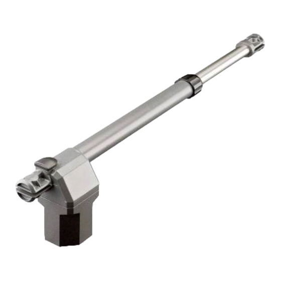
ARES
Quick installation and programming guide
This quick guide is a summary of the complete installation manual. The manual contains safety warnings
IMPORTANT
and other explanations which must be taken into account. The installation manual can be downloaded by
NOTE
going to the "Downloads" section at the Erreka website:
http://www.erreka.com
VERY IMPORTANT:
T C
T h e
c l o s i n g
stopper and the TA
opening stoppers
must be installed in
all cases.
Electrical cabling
A: Main power supply
B: Flashing light
C: Photocells (Tx / Rx)
D: Pushbutton or key switch
E: Operator
F: Antenna
We recommend using an electrolock
for leaf lengths of over 1.8m.
Values for orientation purposes. The
form of the leaf and the presence of
strong wind may bring notable
differences in the values of the
chart.
Elements of the complete installation
E1
Limits on use
BGRBI-BGRBD; BGRBIM-BGRBDM;
BGRRI-BGRRD
300
200
100
1,0 2,0 3,0
E1 E2
E2
300
200
100
English
E1: left model (BGR_I)
E2: right model (BGR_I)
BGRBIL-BGRBDL;
BGRRIL-BGRRDL
1,0
2,0
3,0 4,0
5
Advertisement

Related Manuals for Erreka ARES


Summary of Contents for Erreka ARES
- Page 1 This quick guide is a summary of the complete installation manual. The manual contains safety warnings IMPORTANT and other explanations which must be taken into account. The installation manual can be downloaded by NOTE going to the "Downloads" section at the Erreka website: http://www.erreka.com Elements of the complete installation E1: left model (BGR_I)
- Page 2 Dimensions 47mm 60mm 90mm 35mm 90mm 30mm 70mm BGRB-BGRR: 670-970mm BGRBL-BGRRL: 770-1170mm 50mm C137C Assembly positions and levels Levels A and B determine the opening angle C. Short operator, inward opening (run: 300 mm) A (cm) B (cm) C (º) Long operator, inward opening (run: 400 mm) A (cm) B (cm) C (º)
- Page 3 Components supplied Manual drive Unlocking Locking (manual operation) (motorised operation) mandatory to place the T-cap. C137B Assembly supports should positioned so as the operator forms an angle of 1° with regards horizontal, remaining lower on the gate support side. Mount the operator on the wall support Mount the wall support It is mandatory to place the T-cap.
- Page 4 Electrical connections We recommend using the VIVO-M101(M) switchboard (for single operator installations) and VIVO-M201(M) (for twin operator installations). A1, A2 Operators C1, C2 Capacitors (230V-8μF / 110V-25μF) Gate opening When pressing PUL1 (close), DL5 lights DL5: Gate closing up and the G2/G5 and G3/G6 cable PUL1 Close mini-pushbutton...
Need help?
Do you have a question about the ARES and is the answer not in the manual?
Questions and answers