Erreka ARES Quick Installation And Programming Manual
Hide thumbs
Also See for ARES:
- Installer manual (86 pages) ,
- Quick installation and programming manual (4 pages) ,
- Quick installation and programming manual (4 pages)
Advertisement
ARES
Quick installation and programming guide
This quick guide is a summary of the complete installation manual. The manual contains safety warnings
IMPORTANT
and other explanations which must be taken into account. The installation manual can be downloaded by
NOTE
going to the "Downloads" section at the Erreka website:
http://www.erreka.com/Automatismos/descargaDocumentos.aspx
Electrical cabling
A: Main power supply
B: Flashing light
C: Photocells (Tx / Rx)
D: Pushbutton or key switch
E: Operator
F: Antenna
AE33IPL-AE33DPL
AE3324I-AE3324D
We recommend using an electrolock for leaf
lengths of over 1.8m.
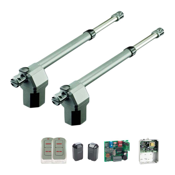
Elements of the complete installation
Limits on use
BGRBI-BGRBD; BGRBIM-BGRBDM;
BGRRI-BGRRD
Values for orientation purposes. The form of the
leaf and the presence of strong wind may bring
notable differences in the values of the chart.
English
BGRBIL-BGRBDL;
BGRRIL-BGRRDL
9
Advertisement
Table of Contents

Related Manuals for Erreka ARES


Summary of Contents for Erreka ARES
- Page 1 This quick guide is a summary of the complete installation manual. The manual contains safety warnings IMPORTANT and other explanations which must be taken into account. The installation manual can be downloaded by NOTE going to the "Downloads" section at the Erreka website: http://www.erreka.com/Automatismos/descargaDocumentos.aspx Elements of the complete installation Electrical cabling...
- Page 2 Assembly positions and levels Levels A and B determine the opening angle C. Short operator, inward opening (run: 300 mm) A (cm) B (cm) C (º) Long operator, inward opening (run: 400 mm) A (cm) B (cm) C (º) Short operator, outward opening (run: 300 mm) A (cm) B (cm) C (º)
- Page 3 Components supplied Manual drive Unlocking Locking (manual operation) (motorised operation) D137A C137B Assembly supports should positioned so as the operator forms an angle of 1° with regards horizontal, remaining lower on the gate support side. Mount the operator on the wall support Mount the wall support Position the gate support Mount the operator on the gate support...
- Page 4 • Select the directions using C1 (A1) and C2 (A2). • Programme C7 for operation without encoder or limit switches (C700). • For the ARES 24V operator, programme C304. • Adjust the thrust in accordance with the weight of the gate (parameter A6).
Need help?
Do you have a question about the ARES and is the answer not in the manual?
Questions and answers