Table of Contents
Advertisement
Quick Links
WARNING!
Read all important information notices on pages 3–5
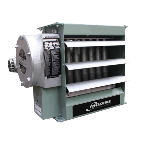
HEX6 Series
Installation, Parts, Service, and Maintenance Manual
60 Hz Models only
approved Locations
C
US
Listed
The Electric Forced Air Heaters are c UL us listed certified for the following locations:
Class I, Division 1 & 2, Groups C & D; Class II, Division 1, Groups E, F & G; Class II,
Division 2, Groups F & G; Class I, Zones 1 & 2, Groups IIA & IIB; Zones 20, 21 & 22;
Temperature Code T3B 329˚F (165˚C) (60 Hz Models)
For details of hazardous locations with potential for explosion, refer to the Canadian
Electrical Code, Part 1, Section 18 or National Electrical Code articles 500–516.
Part No. 11520.Rev.2.01
Issued May 2023 Printed in Canada
2-519.7
5H723536A
Advertisement
Table of Contents

Related Manuals for Modine Manufacturing HEX6 Series


Summary of Contents for Modine Manufacturing HEX6 Series
- Page 1 WARNING! Read all important information notices on pages 3–5 2-519.7 5H723536A HEX6 Series Installation, Parts, Service, and Maintenance Manual 60 Hz Models only approved Locations Listed The Electric Forced Air Heaters are c UL us listed certified for the following locations: Class I, Division 1 &...
-
Page 2: Table Of Contents
WARNING. Improper installation adjustment, alteration, excessive vibration, service, or maintenance can cause property damage, injury or death. Read the installation, WARNING operating and maintenance instructions thoroughly before installing, operating or servicing this equipment. Special Notes The following special notices highlight important information in the installation, operation and maintenance sections. -
Page 3: Heater Maintenance Checklist
Photocopy HEATER MAINTENANCE CHECKLIST this page for reuse. Heater Model Date of Maintenance Serial Number Maintenance Done By Comments WARNING Disconnect heater from power supply at integral Lock the switch in the “OFF” (open) position and/or tag the WARNING disconnect or fuse box before opening enclosures switch to prevent unexpected power application. -
Page 4: Periodic
Photocopy A.2 Periodic this page (before and as required during heating season) for reuse. • Clean • Check Motor Motor for smooth, quiet operation … … Louvers Louvers for proper angle and tightness … … Finned Tubes All explosion-proof covers for tightness …... -
Page 5: Important Notices
IMPORTANT NOTICES do not circumvent this device to operate the heater. WARNING. Read and adhere to the following. Activation of this device necessitates removing the Failure to do so may result in severe or fatal injury. heater immediately from service for evaluation. WARR ANT Y WILL BE VOID. -
Page 6: Troubleshooting Tips
TROUBLESHOOTING TIPS Heater is not operating. heater be removed from service for inspection by authorized personnel. Do not circumvent the Check all fuses in heater control box. overpressure device to operate the heater. Lock Check remote disconnect switch and circuit out/ tag out heater according to site procedures. -
Page 7: Installation
INSTALLATION General Guideline for Installation and Wiring All applicable codes must be adhered to. For optimum Maximum Tilt (Either Direction) heating, the heater should be installed as follows: 1.0" 0.5" (25.4 mm) (12.7 mm) D.1 Mechanical Location There are no obs tructions that may impede the heater’s air inlet or discharge. - Page 8 22 5/8" MAX. (575mm) 22 5/8" MAX. 10 11/16" ±3/16" (575mm) (271 ±5mm) Ø5/8" (Ø15.5mm) 1" NPT MOUNTING HOLES 10 11/16" ±3/16" (For remote r 1" NPT 3 3/4" (4 PLCS) (271 ±5mm) thermostat, if (95.3mm) (For remote room Ø5/8" (Ø15.5mm) 1"...
-
Page 9: Electrical
D.2 Electrical Heater may be supplied with a factory installed WARNING. Disconnect heater from power supply built-in room thermostat (see Figure 8, at integral disconnect or fuse box before opening page 10). On heaters not supplied with this WARNING enclosures or servicing heater. option, it is recommended that a remote room IF INTEGRAL DISCONNECT IS BEING SERVICED, thermostat be used. - Page 10 Final Inspection Optional Built‑in Disconnect & Field Wiring Before application of electrical power: Check that all connections are secured and – comply with the applicable wiring diagram Terminals marked (see Wiring Schematics, page 11) and 1" NPT “T’STAT” code requirements. (Remote room thermostat if Confirm that the power supply is...
-
Page 11: Wiring Schematics
D.3 Wiring Schematics HEX6 WIRING SCHEMATIC 11 11... -
Page 12: Hex6 Technical Data
HEX6 TECHNICAL DATA E.1 60 Hz Electric Heaters Temperature Rise Model °F °C HEX6-208160-030 2700 18.5 23.2 19.0 10.5 12116 HEX6-208160-050 4700 28.1 35.2 31.6 17.6 12117 HEX6-208160-075 7200 40.2 50.2 27.9 15.5 12118 10.0 9690 52.2 65.2 37.2 20.7 12119 HEX6-208160-100*... -
Page 13: Specifications
SPECIFICATIONS F.1 60 Hz Models Nominal kW 12,000 8,000 10,000 7,000 10,000 7,000 10,000 7,000 6,000 Maximum Altitude 3,658 2,438 3,048 2,134 3,048 2,134 3,048 2,134 1,829 @ 70°F (CFM) 1750 3600 Air Flow @ 21°C (m 3 /hr) 1444 2973 6116... - Page 14 Specifications 60 Hz Models Class I, Groups C and D; Class II, Groups E, F and G; Temperature Code Hazardous Location Rating T3B [329°F (165°C)]* NEMA Type 7 & 9. For dry, indoor use only. Do not immerse in water. Do not Enclosures store or use in areas exposed to rain or snow Explosion-proof.
-
Page 15: Parts Assembly Diagram
PARTS ASSEMBLY DIAGRAM See control enclosure assembly diagram (below) Optional Built-in thermostat replaces item See high limit assembly diagram (below) Optional built-in disconnect switch High Limit Control Enclosure Bus-Bar Configuration Bus-Bar Configuration for all 1-Phase Models for all 3-Phase... -
Page 16: Parts List
PARTS LIST Forced Air Electric Heaters Please have model and serial number available before calling Description 2.5 – 4.6 kW 6.3 – 10 kW 12.5 – 20 kW 20.9 – 35 kW Item Core Painted: 12694-02 Painted: 12699-02 Painted: 12704-02 Panel, Bottom S.S.: 12694-03 S.S.: 12699-03... -
Page 17: Repair & Replacement
REPAIR & REPLACEMENT WARNING Disconnect heater from power supply at integral Lock the switch in the (open) position and/or tag the “OFF” disconnect or fuse box before opening enclosures switch to prevent unexpected power application. WARNING or servicing heater. This heater should only be serviced by personnel with IF INTEGRAL DISCONNECT IS BEING SERVICED, heating and hazardous location equipment experience. - Page 18 Motor, Fan, & Fan Guard Side View Remove bolts holding the motor to the motor mount. On units with a built-in thermostat, remove the bolts on the back of the thermostat enclosure. Remove conduit #1 located between motor Fan rotation Air inlet junction box and control enclosure by turning Remove...
- Page 19 Printed Circuit Board After removing the printed circuit board (P.C. Board) bracket assembly from the control enclosure, separate the P.C. Board from the bracket by cutting off the plastic spacers (see 1/16" to 3/16" Figure 9, page 10). (1.6 to 4.8 mm) Reinstall a new factory supplied P.C. Board onto the mounting bracket, using new non- conducting spacers of the same length.
- Page 20 NOTES NOTES...
- Page 21 NOTES NOTES...
- Page 22 NOTES NOTES...
- Page 23 COMMERCIAL WARRANTY BUYER HEREBY ACKNOWLEDGES THAT ITS REMEDIES This Warranty (the “Warranty”) shall apply to Products (as defined below) sold by Modine Manufacturing Company, FOR BREACH OF THIS WARRANTY, EXCLUSIVE OF ALL a Wisconsin corporation (“Seller”) to you (“Buyer”). OTHER REMEDIES PROVIDED BY LAW, ARE LIMITED AS DESCRIBED ABOVE.
- Page 24 All Products 2 YEARS 30 MONTHS Burners, Sheet Metal As Modine Manufacturing Company has a continuous product improvement program, it reserves the right to change design and specifications without notice. Modine Manufacturing Company 1500 DeKoven Avenue Racine, WI 53403 Phone: 1.800.828.4328 (HEAT) ©...
Need help?
Do you have a question about the HEX6 Series and is the answer not in the manual?
Questions and answers