Advertisement
Quick Links
Two-In One Diagrams
Two wiring diagrams are furnished for each circuit configuration
in this manual. Included are a connection diagram at the left
for field installation and a circuit schematic at the right to aid in
continuity and trouble shooting.
Solid lines show pre-wiring performed at the factory; dotted
lines inform the installer of connections required to put the
heater in operation.
NOTE: As indicated in every diagram, all wiring must comply
with the National Electrical Code and all local codes. All
components must agree with their respective power source.
Wiring Diagram Selection
Diagrams are readily identified in the page location index on
the following page. This allows for the correct wiring diagram
to be selected using the model, size, and power code of the
unit heater.
Select the correct wiring diagrams as follows:
1. Determine unit heater model and size.
2. Select power code number from Table 2.3.
3. Reference unit heater model in the Page Location Index
(Table 2.4) with power code number of the corresponding
wiring diagram.
CAUTION
Turn off all power to unit before wiring. Failure to wire this unit
according to this wiring diagram may result in injury to the
installer or user. For deviations, contact factory.
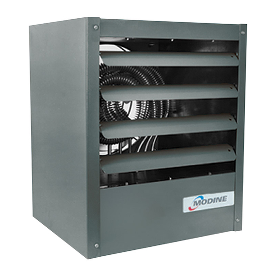
Models HER, VE, PTE electric unit heaters
Abbreviations and Symbols
To facilitate interpretation and enable simplification
the abbreviations and symbols have been selected as
recommended by ANSI (American National Standards
Institute) and NEMA (National Electrical Manufacturers
Association) standards.
XFMR or TR
V
Hz
φ
LC
THERM or TH
G
HTR
H
SW
C
"J" Box
L
H
, H
, etc.
1
2
O.L.C.
R
Rc
VA
X1,X2, etc.
L1, L2, etc.
T1, T2, etc.
Wire Color Coding
BK
BU
R
W
Y
Wire Color Coding
BK
BL
R
W
Y
X1,X2, etc.
L1, L2, etc.
T1, T2, etc.
2-424.6
WIRING DIAGRAMS
Transformer
Volts
Cycle or Hertz
Phase
Limit Control
Thermostat
Ground
Heater
Hot or High
Switch
Common
Junction Box
Low
Transformer Primary Terminals
Overload Contact
Relay
Relay Contact
Volt-Ampere
Transformer Secondary Terminals
Electric Load Terminals
Starter or Motor Terminals
Black
Blue
Red
White
Yellow
Black
Blue
Red
White
Yellow
Transformer Secondary Terminals
Electric Load Terminals
Starter or Motor Terminals
March, 2016
Advertisement

Subscribe to Our Youtube Channel
Summary of Contents for Modine Manufacturing VE Series
- Page 1 2-424.6 March, 2016 WIRING DIAGRAMS Models HER, VE, PTE electric unit heaters Two-In One Diagrams Abbreviations and Symbols Two wiring diagrams are furnished for each circuit configuration in this manual. Included are a connection diagram at the left To facilitate interpretation and enable simplification for field installation and a circuit schematic at the right to aid in the abbreviations and symbols have been selected as continuity and trouble shooting.
- Page 2 2-424.5 — WIRING DIAGRAMS MODELS HER, VE, PTE Table 2.1 Unit Power Requirements (AMPS) - HER Models Power Supply HER 30 HER 50 HER 75 HER100 HER125 HER150 HER200 HER250 208/1 14.9 24.5 36.5 49.4 240/1 12.9 21.3 31.7 42.9 208/3 14.3 21.3...
- Page 3 2-424.5 — WIRING DIAGRAMS MODELS HER, VE, PTE 5H70253A1 208V or 240V, single-phase power supply, 3kw, 5kw, 7.5kw Horizontal Models...
- Page 4 2-424.5 — WIRING DIAGRAMS MODELS HER, VE, PTE 5H70253A2 REV F 208V or 240V, single-phase power supply, 10kw Horizontal Model...
- Page 5 2-424.5 — WIRING DIAGRAMS MODELS HER, VE, PTE 5H70253A4 REV E 208V or 240V, three-phase power supply, 3kw, 5kw, 7.5kw, 10kw, 12.5kw, 15kw Horizontal Models...
- Page 6 2-424.5 — WIRING DIAGRAMS MODELS HER, VE, PTE 5H70253A5 208V, three-phase power supply, 15kw Horizontal Model...
- Page 7 2-424.5 — WIRING DIAGRAMS MODELS HER, VE, PTE 5H70253A6 208V or 240V, three-phase power supply, 20kw, 25kw Horizontal Models...
- Page 8 2-424.5 — WIRING DIAGRAMS MODELS HER, VE, PTE 5H70253A7 480V or 600V, three-phase power supply, 3kw, 5kw thru 25kw Horizontal Models...
- Page 9 2-424.5 — WIRING DIAGRAMS MODELS HER, VE, PTE 5H70253A8 240V, single-phase power supply, 5kw, 7.5kw, 10kw Vertical Models...
- Page 10 2-424.5 — WIRING DIAGRAMS MODELS HER, VE, PTE 5H70253A9 208V or 240V, three-phase power supply, 5kw, 7.5kw, 10kw Vertical Models...
- Page 11 2-424.5 — WIRING DIAGRAMS MODELS HER, VE, PTE 5H70253A10 480V or 600V, three-phase power supply, 5kw, 7.5kw, 10kw Vertical Models...
- Page 12 2-424.5 — WIRING DIAGRAMS MODELS HER, VE, PTE 5H70253A11 REV H 480V or 600V, three-phase power supply, 30kw, 40kw, and 50kw Vertical and Power Throw Models...
- Page 13 2-424.5 — WIRING DIAGRAMS MODELS HER, VE, PTE 5H70253A12 208V or 240-volt, three-phase power supply, 15kw, 20kw Vertical Models...
- Page 14 2-424.5 — WIRING DIAGRAMS MODELS HER, VE, PTE 5H70253A13 480V or 600-volt, three-phase power supply, 15kw, 20kw, 25kw Vertical Models...
- Page 15 THIS PAGE LEFT BLANK INTENTIONALLY...
- Page 16 For SERVICE contact your local qualified installation and service contractor or appropriate utility company. As Modine Manufacturing Company has a continuous product improvement program, it reserves the right to change design and specifications without notice. Modine Manufacturing Company • 1500 DeKoven Avenue • Racine, Wisconsin 53403-2552 Tel: 1.800.828.4328 (HEAT) •...


Need help?
Do you have a question about the VE Series and is the answer not in the manual?
Questions and answers