Table of Contents
Advertisement
Quick Links
WARNING!
Read all important information notices on pages 3–5
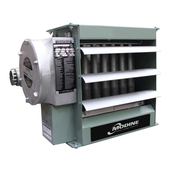
HEX5 Series
Installation, Parts, Service, and Maintenance Manual
60 Hz Models only
Model Coding
HEX5
FX5 ‑ 480
Model
Heater Voltage
Series
208V, 240V,
480V, 600V
5th Generation
Phase
1, 3
approved Locations
C
US
Listed
The Electric Forced Air Heaters are c UL us listed certified for the following locations:
Class I, Divisions 1 & 2, Groups C & D; Class II, Division 1, Groups E, F & G; Class II,
Division 2, Groups F & G; Class I, Zones 1 & 2, Groups IIA & IIB; Temperature Code
T3B 329˚F (165˚C)
For details of hazardous locations with potential for explosion, refer to the Canadian
Electrical Code, Part 1, Section 18 or National Electrical Code articles 500–516.
3
60 ‑ 350 ‑ W ‑ T
Hertz
Welded Core
50, 60
60
Heater Kilowatts
T – XT-311 Thermostat with slim
junction box
XT-411 Thermostat with large
junction box
D – Built-in disconnect
P – Built-in pilot light
S – 3-way switch
Part No. 11520.Rev.2.00
ISO 9001
2-519.6
5H723536A
H – Unit with high "off" de-energized
ambient temperatures
C – Heresite
coating
®
A – Stainless steel cabinet
U – Continuous fan
B – Low ambient option -50°F (-50°C)
L – Large junction box
Issued June 2017
Printed in Canada
Advertisement
Table of Contents

Related Manuals for Modine Manufacturing HEX5 Series


Summary of Contents for Modine Manufacturing HEX5 Series
- Page 1 ISO 9001 WARNING! 2-519.6 Read all important information notices on pages 3–5 5H723536A HEX5 Series Installation, Parts, Service, and Maintenance Manual 60 Hz Models only Model Coding HEX5 FX5 ‑ 480 60 ‑ 350 ‑ W ‑ T Model Heater Voltage...
-
Page 2: Table Of Contents
TABLE OF CONTENTS A. Heater Maintenance Checklist Preventative Maintenance Grid ................3 Periodic ........................4 Annual ........................4 B. Important Notices C. Troubleshooting Tips D. Installation Mechanical ......................7 Electrical ......................9 Wiring Schematics ..................... 11 E. HEX5 Technical Data 60 Hz Electric Heaters ..................12 F. -
Page 3: Heater Maintenance Checklist
Photocopy HEATER MAINTENANCE CHECKLIST this page for reuse. Heater Model Date of Maintenance Serial Number Maintenance Done By Comments WARNING Lock the switch in the “OFF” (open) position and/or tag the Disconnect heater from power supply at integral disconnect or fuse switch to prevent unexpected power application. -
Page 4: Periodic
Photocopy Periodic (before and as required during heating season) this page for reuse. • Clean • Check Motor Motor for smooth, quiet operation … … Louvers Louvers for proper angle and tightness … … Finned Tubes All explosion-proof covers for tightness …... -
Page 5: Important Notices
IMPORTANT NOTICES Do not operate heater in ambient temperatures above WARNING 104°F (40°C). Use factory approved replacement parts only. Read and adhere to the following. Failure to do so may result in severe or fatal injury. WARR ANT Y WILL BE VOID. See applicable electrical codes for seal requirements in field installed conduits. -
Page 6: Troubleshooting Tips
TROUBLESHOOTING TIPS Heater is not operating. The core may be dirty, fan may not be working or may be turning the wrong way (the fan must rotate Check all fuses in heater control box. clockwise as seen from the front of the unit) objects Check remote disconnect switch and circuit breaker. -
Page 7: Installation
INSTALLATION General Guideline for Installation and Wiring All applicable codes must be adhered to. For optimum heating, the Maximum Tilt (Either Direction) heater should be installed as follows: 1.0" 0.5" (25.4 mm) (12.7 mm) Mechanical Location There are no obs tructions that may impede the heater’s air inlet or discharge. - Page 8 22 5/8" MAX. (575mm) 10 11/16" ±3/16" (271 ±5mm) Ø5/8" (Ø15.5mm) 1" NPT MOUNTING HOLES (For remote r 3 3/4" (4 PLCS) thermostat, if (95.3mm) Dimensional Tolerances +1/8" [+3 mm] 22 5/8" (575 mm max.) Unless otherwise specified. 10 11/16"±3/16" ø5/8"...
-
Page 9: Electrical
Electrical Heater may be supplied with a factory installed built-in room thermostat (see Figure 8, page 10). WARNING On heaters not supplied with this option, it is Disconnect heater from power supply at integral disconnect or recommended that a remote room thermostat fuse box before opening enclosures or servicing heater. - Page 10 Final Inspection Optional Built‑in Disconnect & Field Wiring Before application of electrical power: – Check that all connections are secured and comply with the applicable wiring diagram Terminals (see Wiring Schematics, page 11) and code marked 1" NPT requirements. “T’STAT” (Remote room thermostat if –...
-
Page 11: Wiring Schematics
Wiring Schematics 1‑Phase 1‑Phase with Optional Pilot Light and 3‑Way Switch Optional integral Transformer* Element Contactor disconnect Optional integral Optional 3-Way Switch disconnect Optional Fan B pilot light Auto A&C Fuse Transformer* Optional pilot light Contactor Auto-reset Auto-reset Optional room temperature temperature thermostat... -
Page 12: Hex5 Technical Data
HEX5 TECHNICAL DATA 60 Hz Electric Heaters Temperature Model Rise °F °C HEX5-208160-030 2700 18.5 23.2 19.0 10.5 12116 HEX5-208160-050 4700 28.1 35.2 31.6 17.6 12117 HEX5-208160-075 7200 40.2 50.2 27.9 15.5 12118 HEX5-208160-100* 10.0 9690 52.2 65.2 37.2 20.7 12119 HEX5-208360-030 2700... - Page 13 Temperature Model Rise °F °C HEX5-480160-030 ** 2700 19.0 10.5 12129 HEX5-480160-050 ** 4700 11.2 14.0 31.6 17.6 12130 HEX5-480160-075 ** 7200 16.4 20.5 27.9 15.5 12131 HEX5-480160-100 ** 10.0 9700 21.6 27.0 37.2 20.7 12132 HEX5-480160-150 ** 15.0 14400 32.1 40.1 27.1...
-
Page 14: Specifications
SPECIFICATIONS 60 Hz Models Nominal kW 12,000 8,000 10,000 7,000 10,000 7,000 10,000 7,000 6,000 Maximum Altitude 3,658 2,438 3,048 2,134 3,048 2,134 3,048 2,134 1,829 @ 70°F (CFM) 1750 3600 Air Flow @ 21°C (m 3 /hr) 1444 2973 6116 Horizontal Air Throw... - Page 15 Specifications for 60 Hz Models Class I, Groups C and D; Class II, Groups E, F and G; 1. Hazardous Location Rating Temperature Code T3B [329°F (165°C)]* NEMA Type 7 & 9. For dry, indoor use only. Do not immerse in 2.
-
Page 16: Parts Assembly Diagram
PARTS ASSEMBLY DIAGRAM See control enclosure assembly diagram (below) Optional Built-in thermostat replaces item #16 See high limit assembly diagram (below) Optional built-in disconnect switch kit Slim Control Enclosure Large Control Enclosure High Limit Bus‑Bar Configuration for Bus‑Bar Configuration all 1‑Phase Models for all 3‑Phase 16 16... -
Page 17: Parts List
PARTS LIST Forced Air Electric Heaters Please have model and serial number available before calling Item Description 2.5 – 4.6 kW 6.3 – 10 kW 12.5 – 20 kW 20.9 – 35 kW Core Painted: 12694-02 Painted: 12699-02 Painted: 12704-02 Panel, Bottom S.S.: 12694-03 S.S.: 12699-03... -
Page 18: Repair & Replacement
REPAIR & REPLACEMENT WARNING Lock the switch in the “OFF” (open) position and/or tag the Disconnect heater from power supply at integral disconnect or fuse switch to prevent unexpected power application. box before opening enclosures or servicing heater. This heater should only be serviced by personnel with heating IF INTEGRAL DISCONNECT IS BEING SERVICED, verify that and hazardous location equipment experience. - Page 19 Motor, Fan, & Fan Guard Side View Remove bolts holding the motor to the motor mount. On units with a built-in thermostat, remove the bolts on the back of the thermostat enclosure. Remove conduit #1 located between motor junction box and control enclosure by turning it in the Fan rotation Air inlet direction illustrated (see Figure 14, page 19).
- Page 20 Printed Circuit Board After removing the printed circuit board (P.C. Board) bracket assembly from the control enclosure, separate the P.C. Board from the bracket by cutting off the plastic spacers (see Figure 9, page 10). 1/16" to 3/16" (1.6 to 4.8 mm) Reinstall a new factory supplied P.C.
- Page 21 NOTES...
- Page 22 NOTES...
- Page 23 NOTES...
- Page 24 Burners High Intensity Infrared Units sheet metal Parts All Products As Modine Manufacturing Company has a continuous product improvement program, it reserves the right to change design and specifications without notice. Commercial Products group Modine Manufacturing Company 1500 DeKoven Avenue Racine, WI 53403 Phone: 1.800.828.4328 (HEAT)
Need help?
Do you have a question about the HEX5 Series and is the answer not in the manual?
Questions and answers