Table of Contents
Advertisement
Quick Links
Advertisement
Table of Contents

Related Manuals for Vertiv eSure C48/27-375B


Summary of Contents for Vertiv eSure C48/27-375B
- Page 1 +27 VDC Vertiv™ eSure™ Bullet Converter Installation and User Manual Specification Number: 1C4827375B Model Number: C48/27-375B Note: P/N 60147273 includes +27 VDC Vertiv™ eSure™ Bullet Converter Spec. No. 1C4827375B and associated components.
- Page 2 +27 VDC Vertiv™ eSure™ Bullet Converter Installation and User Manual The information contained in this document is subject to change without notice and may not be suitable for all applications. While every precaution has been taken to ensure the accuracy and completeness of this document,...
-
Page 3: Table Of Contents
+27 VDC Vertiv™ eSure™ Bullet Converter Installation and User Manual TABLE OF CONTENTS Admonishments Used in this Document ..............v Important Safety Instructions ..................vi Safety Admonishments Definitions ............................ vi General Safety ......................................vi Voltages ........................................vi AC Input Voltages ................................vi DC Input Voltages ................................ - Page 4 +27 VDC Vertiv™ eSure™ Bullet Converter Installation and User Manual 2.3 Environmental Ratings ..............................10 2.4 Compliance Information ..............................10 2.5 Standard Features ................................. 11 2.6 Mechanical Specifications ............................. 12 3 Installation ........................13 3.1 General Requirements ............................... 13 3.2 Installing the eSure™ +27 VDC Bullet Converter ..................13 4 Making Electrical Connections ................
-
Page 5: Admonishments Used In This Document
+27 VDC Vertiv™ eSure™ Bullet Converter Installation and User Manual Admonishments Used in this Document DANGER! Warns of a hazard the reader will be exposed to that will likely result in death or serious injury if not avoided. (ANSI, OSHA) WARNING! Warns of a potential hazard the reader may be exposed to that could result in death or serious injury if not avoided. -
Page 6: Important Safety Instructions
Voltages AC Input Voltages DANGER! The system the +27 VDC Vertiv™ eSure™ Bullet Converter is installed in operates from AC input voltage capable of producing fatal electrical shock. DC Input Voltages DANGER! The +27 VDC Vertiv™ eSure™ Bullet Converter operates from DC input voltage. -
Page 7: Dc Output And Battery Voltages
+27 VDC Vertiv™ eSure™ Bullet Converter Installation and User Manual DC Output and Battery Voltages DANGER! The system the +27 VDC Vertiv™ eSure™ Bullet Converter is installed in produces DC power and may have a battery source connected to it. Although the DC voltage is not hazardously high, the rectifiers and/or battery can deliver large amounts of current. -
Page 8: Static Warning
+27 VDC Vertiv™ eSure™ Bullet Converter Installation and User Manual Static Warning This equipment contains static sensitive components. The warnings listed below must be observed to prevent damage to these components. Disregarding any of these warnings may result in personal injury or damage to the equipment. -
Page 9: Avertissements Utilisés Dans Ce Document
+27 VDC Vertiv™ eSure™ Bullet Converter Installation and User Manual Avertissements utilisés dans ce document DANGER! Signale au lecteur un risque auquel il sera exposé et qui, s’il n’est pas évité, pourrait entraîner des blessures graves, voire mortelles. (ANSI, OSHA) AVERTISSEMENT! Signale au lecteur un risque potentiel auquel il pourrait être exposé... -
Page 10: Consignes De Sécurité Importantes
+27 VDC Vertiv™ eSure™ Bullet Converter Installation and User Manual Consignes de sécurité importantes Définition des avertissements de sécurité Pour consulter les définitions des avertissements de sécurité utilisés dans ce document, reportez-vous à la section « Avertissements utilisés dans ce document » à la page v. -
Page 11: Tensions D'alimentation En Entrée C.c
+27 VDC Vertiv™ eSure™ Bullet Converter Installation and User Manual Tensions d’alimentation en entrée c.c. DANGER! Le convertisseur eSure™ Bullet +27 VDC fonctionne à partir d'une tension d'entrée CC. Bien que la tension continue ne soit pas dangereusement élevée, la puissance d'entrée peut fournir de grandes quantités de courant. -
Page 12: Manipulation D'équipements Contenant Des Composants Sensibles À
+27 VDC Vertiv™ eSure™ Bullet Converter Installation and User Manual Manipulation d’équipements contenant des composants sensibles à l’électricité statique ALERTE! L’installation ou le retrait d’équipements contenant des composants sensibles à l’électricité statique exigent une manipulation délicate. Avant de manipuler tout équipement contenant des composants sensibles à l’électricité... -
Page 13: L'électricité Statique
+27 VDC Vertiv™ eSure™ Bullet Converter Installation and User Manual Mise en garde concernant l’électricité statique Cet équipement contient des composants sensibles à l’électricité statique. Les mises en garde ci-dessous doivent être observées afin d’empêcher tout endommagement de ces composants. Le non-respect de ces mises en garde pourrait entraîner des blessures corporelles ou endommager l’équipement. - Page 14 +27 VDC Vertiv™ eSure™ Bullet Converter Installation and User Manual This page intentionally left blank. Proprietary and Confidential © 2024 Vertiv Group Corp.
-
Page 15: Introduction
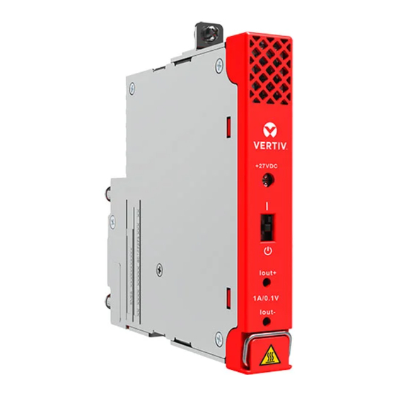
1 Introduction 1.1 Overview The +27 VDC Vertiv™ eSure™ Bullet Converter (Model C48/27-375B, Spec. No. 1C4827375B) is a compact DC/DC converter unit which offers efficient power conversion. It operates from a nominal‑48 VDC source to provide regulated +27 VDC to the load for continuous operation to -41VDC input. -
Page 16: What Is In The Box
Support mounting bracket kits have been designed to easily install the Model C48/27-375B +27 VDC Vertiv™ eSure™ Bullet Converter into the power systems listed in Table 2. A support mounting bracket kit must be used for grounding and mechanical support. The various support mounting bracket kits available are listed in Table 3. - Page 17 +27 VDC Vertiv™ eSure™ Bullet Converter Installation and User Manual Table 2: Associated Power Systems Spec. No. Description 548066 -48 VDC Stand-Alone Distribution Panel, 19-inch wide 548067 -48 VDC Stand-Alone Distribution Panel, 23-inch wide 10009822 -48 VDC Stand-Alone Distribution Panel, 23-inch wide (w/ adapters)
- Page 18 +27 VDC Vertiv™ eSure™ Bullet Converter Installation and User Manual Table 3: Power System Mounting Bracket Kits Mounting Bracket Description Kit P/N For use with a List AA (24-position bullet) distribution panel installed in a Spec. No. 582127000 power system.
- Page 19 +27 VDC Vertiv™ eSure™ Bullet Converter Installation and User Manual Table 4: Additional Material for Systems to be Equipped with +27 VDC Vertiv™ eSure™ Bullet Converter Description 21-position return bus bar for use with Spec. No. 582137100 List 20 installed prior to 565788 January, 2020.
- Page 20 +27 VDC Vertiv™ eSure™ Bullet Converter Installation and User Manual Figure 1: C48/27-375B Illustration 3.13 0.43 [79,6] [11,0] 4.22 [107,2] Iout 4.35 [110,4] Alarm 1.94 1.28 [49,3] [32,4] 0.365 0.28 4.64 0.06 [9,27] [7,0] [117,9] [1,6] 5.30 (3X) 0.73 [134,5]...
-
Page 21: Specifications
+27 VDC Vertiv™ eSure™ Bullet Converter Installation and User Manual 2 Specifications 2.1 DC Output Ratings Nameplate Rating: +27 VDC/13.9A, 375W maximum. Output Power: See Figure 2. Output Current: 13.9 amps maximum. Output Voltage: Nominal +27 VDC. Output voltage is non-adjustable. -
Page 22: Dc Input Ratings
Inrush Current: The peak value of the input inrush current shall not exceed 2.0 times the peak value of the maximum steady-state input current at 25 °C and shall not trigger the +27 VDC Vertiv™ eSure™ Bullet Converter’s internal input fault protection device(s). No damage to connection points when inserted into a live bus. - Page 23 +27 VDC Vertiv™ eSure™ Bullet Converter Installation and User Manual Table 5: Typical Input/Output Data Vin (VDC) % load Iin (ADC) Vo (VDC) Io (ADC) Wloss (W) BTU/hour 42.32 0.00% 0.07 27.88 2.96 10.10 42.27 20.50% 1.99 27.26 2.82 0.914 7.25...
-
Page 24: Environmental Ratings
+27 VDC Vertiv™ eSure™ Bullet Converter Installation and User Manual 2.3 Environmental Ratings Operation Temperature Range: -40 °C to +75 °C (-40 °F to +167 °F). Storage Ambient Temperature Range: -40 °C to +70 °C (-40 °F to +158 °F). -
Page 25: Standard Features
Input Protection: Fusing: A non-user replaceable fuse providing branch-circuit protection is located in the negative input lead of the +27 VDC Vertiv™ eSure™ Bullet Converter. The fuse rating is 20A. Low Input Voltage Protection: The +27 VDC Vertiv™ eSure™ Bullet Converter shuts down at low input voltage. -
Page 26: Mechanical Specifications
Bullet Converter is extended to the distribution-device alarm- termination strip on the distribution panel. Local Controls: A switch is provided on the front of the +27 VDC Vertiv™ eSure™ Bullet Converter to enable/disable operation. Local Test Points: Test points are provided on the front of the +27 VDC Vertiv™... -
Page 27: Installation
Converter NOTE! The +27 VDC Vertiv™ eSure™ Bullet Converter can be inserted or removed with power applied (hot swappable) as long as the +27 VDC Vertiv™ eSure™ Bullet Converter is inserted/removed with the enable/disable switch in the disabled position. See Figure 8 on page 24. - Page 28 Bullet Converter is recommended to be installed on the right-hand side of the panel. If the +27 VDC Vertiv™ eSure™ Bullet Converter is to be installed for a newly connected load, connect the load and load return cables to the distribution panel for the position to be occupied by the +27 VDC Vertiv™...
- Page 29 +27 VDC Vertiv™ eSure™ Bullet Converter Installation and User Manual If the +27 VDC Vertiv™ eSure™ Bullet Converter is to replace an existing circuit breaker, remove the circuit breaker and verify the load and return cables for the position are wired and labeled correctly. It may be advantageous to loosen and temporarily move the load side cables for easier access to the hardware on the return landing position studs.
- Page 30 +27 VDC Vertiv™ eSure™ Bullet Converter Installation and User Manual Route the return wire (P/N 564330) down and behind the +27 VDC Vertiv™ eSure™ Bullet Converter’s front mounting bracket, then connect it to the +27 VDC Vertiv™ eSure™ Bullet Converter. See Figure 5. Orient the white square on the return wire Faston receptacle’s locking tab as shown in Figure 5.
- Page 31 +27 VDC Vertiv™ eSure™ Bullet Converter Installation and User Manual Figure 4: Connecting +27 VDC Vertiv™ eSure™ Bullet Converter Return Wire (P/N 564330) and Return Wire Extension (P/N 565752 or 566207) to the +27 VDC Vertiv™ eSure™ Bullet Converter Return Wire Faston Tab (P/N 565990 shown, P/N 10086492 also available) Proprietary and Confidential ©...
- Page 32 +27 VDC Vertiv™ eSure™ Bullet Converter Installation and User Manual Figure 5: Connecting +27 VDC Vertiv™ eSure™ Bullet Converter Return Wire (P/N 564330) to the +27 VDC Vertiv™ eSure™ Bullet Converter Ensure the enable/disable switch on the +27 VDC Vertiv™ eSure™ Bullet Converter is in the disable (down) position.
- Page 33 Place the enable/disable switch on the +27 VDC Vertiv™ eSure™ Bullet Converter to the enable position. See Figure 8 on page 24. If two or three +27 VDC Vertiv™ eSure™ Bullet Converters are connected in parallel to a load that exceeds 375 watts peak, they should be switched on simultaneously.
-
Page 34: Making Electrical Connections
+27 VDC Vertiv™ eSure™ Bullet Converter Installation and User Manual 4 Making Electrical Connections 4.1 Important Safety Instructions DANGER! Adhere to the “Important Safety Instructions” starting on page vi and those listed in the power system manual. 4.2 Wiring Considerations... -
Page 35: Electrical Connections
4.3 Electrical Connections Procedure Output leads from the +27 VDC Vertiv™ eSure™ Bullet Converter are connected to the system’s return bar and to the respective load position for the distribution position into which the device is installed. Refer to the instructions furnished with the power system for wiring to a load position. -
Page 36: Converter Operation
5.2 Checking +27 VDC Vertiv™ eSure™ Bullet Converter Status Procedure Observe the status of the +27 VDC Vertiv™ eSure™ Bullet Converter front panel local indicator. If operating normally, this indicator should be illuminated green. See Figure 8. Proprietary and Confidential © 2024 Vertiv Group Corp. -
Page 37: Operation
Refer to Figure 8. Indicator There is one (1) indicator located on the +27 VDC Vertiv™ eSure™ Bullet Converter’s front panel. Refer to Table 7 for the function of this indicator. Refer also to Table 7 for the alarm contact state for each indicator function. - Page 38 +27 VDC Vertiv™ eSure™ Bullet Converter Installation and User Manual Figure 8: Local Indicator, Test Points, and Switch Location and Identification Table 7: Front Panel Indicator Function and Alarm Contact State Condition LED Color Alarm Contact State +27 VDC Vertiv™ eSure™ Bullet Converter is within...
- Page 39 +27 VDC Vertiv™ eSure™ Bullet Converter Installation and User Manual Table 8: Test Point Conversion Table Test Point Voltage Measurement (VDC) Actual Output Current (Amps) 0.00 0.00 0.10 1.00 0.20 2.00 0.30 3.00 0.40 4.00 0.50 5.00 0.60 6.00 0.70 7.00...
-
Page 40: Troubleshooting And Repair
Refer to Section 4154 (provided with your customer documentation) for support contact information. 7.3 Troubleshooting 7.3.1 +27 VDC Vertiv™ eSure™ Bullet Converter Fault Symptoms and Troubleshooting The fault indicators that can be displayed by the +27 VDC Vertiv™ eSure™ Bullet Converter are as follows. • Status Indicator (Red) •... -
Page 41: Repair
When a trouble symptom is localized to a faulty +27 VDC Vertiv™ eSure™ Bullet Converter, the +27 VDC Vertiv™ eSure™ Bullet Converter is to be replaced in its entirety. No attempt should be made to troubleshoot or repair individual components inside the +27 VDC Vertiv™... -
Page 42: Important Safety Instructions
WARNING! The +27 VDC Vertiv™ eSure™ Bullet Converter and front mounting bracket becomes very hot during +27 VDC Vertiv™ eSure™ Bullet Converter operation at heavy loads. Wear heat resistant gloves or allow the +27 VDC Vertiv™ eSure™ Bullet Converter to cool down before removing. - Page 43 +27 VDC Vertiv™ eSure™ Bullet Converter Installation and User Manual Place the replacement +27 VDC Vertiv™ eSure™ Bullet Converter front panel enable/disable switch to the enable position. Observe the status of the replacement +27 VDC Vertiv™ eSure™ Bullet Converter front panel local indicator. If operating normally, this indicator should be illuminated green.
- Page 44 +27 VDC Vertiv™ eSure™ Bullet Converter Installation and User Manual This page intentionally left blank. Proprietary and Confidential © 2024 Vertiv Group Corp.
- Page 45 +27 VDC Vertiv™ eSure™ Bullet Converter Installation and User Manual Connect with Vertiv on Social Media https://www.facebook.com/vertivI https://www.instagram.com/vertiv/ https://www.linkedin.com/company/vertiv/ https://www.twitter.com/vertiv/ Proprietary and Confidential © 2024 Vertiv Group Corp.
- Page 46 Vertiv.com | Vertiv Headquarters, 505 N Cleveland Ave, Westerville, OH 43082, USA © 2024 Vertiv Group Corp. All rights reserved. Vertiv™ and the Vertiv logo are trademarks or registered trademarks of Vertiv Group Corp. All other names and logos referred to are trade names, trademarks or registered trademarks of their respective owners.
Need help?
Do you have a question about the eSure C48/27-375B and is the answer not in the manual?
Questions and answers