Advertisement
Quick Links
Advertisement

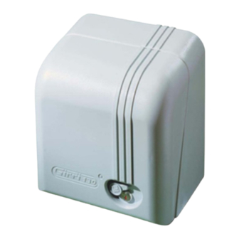
Summary of Contents for fadini GIRRI 130
- Page 1 INSTALLATION MANUAL ®...
- Page 2 ELECTRO-MECHANICAL SLIDING GATE OPERATOR CUT AWAY SIDE VIEW OF THE ELECTRO-MECHANICAL OPERATOR GIRRI 130 FOR SLIDING GATES COVER LID BACK COVER OPTIONAL FAN COVER ELPRO 15 exp CONTROL BOX OPTIONAL COOLING FAN GENERAL LINE SWITCH 137 ELECTRIC MOTOR CUT OFF LIMIT...
- Page 3 FIXING DETAIL WITH PARTS LAYOUT OF THE ELECTRO-MECHANICAL GATE OPERATOR GIRRI 130 INSTRUCTIONS FOR THE INSTALLATION OF GIRRI 130 ON TO SLIDING GATES To achieve a perfect application and performance of GIRRI 130, you must follow the steps and the drawings here below: COVER...
- Page 4 4 long bolts so that the threads are all out. Set the plate horizontally levelled as shown in the illustration at 80 mm from REFERENCE LINE the gate. Corner “A” of GIRRI 130 base plate is to coincide with the reference line drawn on the fixing base plate. FIXING...
- Page 5 REMOVE THE LID FROM THE COVER LOCK WITH KEYS GATE WHEEL TIGHTEN FOR AUTOMATIC MOVEMENTS RELEASE KNOB PIC. 5 Remove the cover to lock or release the operator (Pic. 5-6). PIC. 6 To release for manual operations 3 turns anti-clockwise. FIXING NUT OPERATOR BASE PLATE Once fixed the operator on its concrete mounting you can carry...
- Page 6 9 - RECEIVER TRIFO 11 PHOTOCELL 4 - TRANSMITTER TRIFO 11 PHOTOCELL 10 - TOOTHED RACK 5 - ELECTRIC CABLES 11 - OPERATOR GIRRI 130 6 - AERIAL A 43 12 - QUARTZ TRANSMITTER ASTRO 43/2 TR PIC. 9 N.W: CARRY OUT A RISK ANALYSIS IN COMPLIANCE WITH EN 12445 AND EN 12453 NORMS AND FIT ANY SAFETY DEVICE WHERE REQUIRED.
-
Page 7: Identification Plate
For the application of the “CE” mark it is recommended to have the operator fitted with item No. 137 the line switch. - This switch is fitted on the customer’s request if an order for GIRRI 130 with CE sticker on it is received. ELECTRICALLY OPERATED GATES ®... - Page 8 Standard relays would affect the micro-processor. 3 4 5 6 NOTE WELL: THIS PANEL IS TESTED TO OPERATE GATES ONLY THROUGH FADINI ACCESSORIES. NO WARRANTY IS ACKNOWLEDGED BY THE MANUFACTURER IN CASE THAT OTHER ACCESSORIES ARE USED OR NON CONFORMING...
- Page 9 • Please note that a low voltage cut off switch is fitted to the right side of the control box. The contacts are closed when EARTH LOGIC SWITCH the operator lid is put back (Pic. 14). • Instead of the low voltage cut off microswitch (ie. LOGIC switch) see Pic.
- Page 10 PIC. 17 The “electronic” torque control of the operator, ie. an “adjustable pushing power” for safety reasons, is achieved by adjusting a switch which is positioned near the electric cables coming out from the transformer (Pic. 17). The adjustment of the pushing power, ie the quantity of electric current which is supplied to the motor, is controlled by the transformer which is incorporated in the electronic P.C.
- Page 11 YELLOW/GREEN MOTOR CAPACITOR BLUE 230 VOLT 20 µF 50/60 Hz CAPACITOR HIGH VOLTAGE 16 15 14 HOW TO REVERSE 16 15 14 THE DIRECTION OF THE ELECTRIC MOTOR COMMON PIC. 20 If, during the first run test, you realize that the electric motor turns in the wrong direction and the limit switch rod is not activated (that is when the limit switch rod is pushed in the same direction of the gate, which does not stop), you must remove the cover and reverse the position of the electric motor wires 16 and 14, change over No.
-
Page 12: Technical Specifications
Distributor’s box s.n.c. AUTOMATIC GATE MANUFACTURERS The manufacturers reserve the right to change the products without any previous notice Via Mantova, 177/A - 37053 Cerea (Verona) Italy - Tel. 0442 330422 r.a. - Fax 0442 331054 - e-mail: info@fadini.net - www.fadini.net...


Need help?
Do you have a question about the GIRRI 130 and is the answer not in the manual?
Questions and answers