Table of Contents
Advertisement
Quick Links
Monitor and manage environmental and security conditions over IP.
Provides early warnings before critical events turn into disaster.
Environment Monitoring
Temperature
„
Humidity
„
Water Leaks
„
Air Flow
„
Alert Notifications
Email
„
SNMP
„
Key Features
Sensors supported by a single E-MICRO:
„
1 integrated temperature/humidity combination sensor
•
2 RJ45 ports for external temperature/humidity sensors
•
2 digital inputs sensitive to contact closure
•
Dual DC power provides dual redundancy.
„
Available with optional built-in Power over Ethernet.
„
Sensors are hot pluggable.
„
Monitor (ping) up to 4 IP network devices – alerts are sent if devices are
„
not responding.
Create multiple alerts for any installed sensor.
„
Sensor conditions can be configured to trigger alerts by themselves, and/
„
or be used in combination with other alerts to trigger one Smart Alert.
Configure up to 32 alerts, and one Smart Alert.
„
Alerts are posted in message log, which is accessible through Web user
„
interface.
Supports 4 IP network video cameras for live view of any facility.
„
Integrates with various Open Source SNMP monitoring packages –
„
Nagios.
The unit can be polled via SNMP.
„
Optional intuitive graphical management software provides an easy-to-
„
use, unified interface for both monitoring and configuring up to 3,000
ENVIROMUX units and all connected sensors.
Optional Android App provides an easy-to-use interface for monitoring
„
sensor statuses and acknowledging/dismissing sensor alerts from an
unlimited number of E-MICRO units.
Integrated mounting brackets for easy surface/wall mounting.
„
Optional DIN mounting available.
•
Security: HTTPS, TLS v1.2, AES 256-bit encryption, 16-character
„
username/password authentication, user account restricted access rights.
Use in data centers, co-lo sites, web hosting facilities, telecom switching
„
sites, POP sites, server closets, or any unmanned area that needs to be
monitored.
NETWORK
R
TECHNOLOGIES
INCORPORATED
Micro Environment Monitoring System /
Remote Temperature/Humidity Sensor over IP
Power
„
Motion / Intrusion
„
Vibration
„
Smoke / Carbon Monoxide
„
Web Page
„
SMS
„
1.800.RGB.TECH (800.742.8324)
To l l F r e e : U S & C a n a d a
• Integrated temp/humidity sensor, 2 RJ45
temp/humidity ports, 2 digital inputs
• Power over Ethernet option
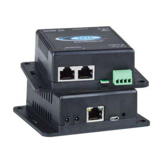
The ENVIROMUX® Micro Environment Monitoring System monitors
critical environmental conditions, such as temperature, humidity, liquid water
presence, power, intrusion, and smoke. When a sensor goes out of range of
a configurable threshold, the system will notify you via email, web page,
network management (SNMP), and/or SMS messages (via email-to-SMS).
The system functions independently or as an IP-connected remote sensor for
the E-2D/5D/16D. It features an integrated temperature/humidity sensor, two
RJ45 sensor ports for external temperature/humidity sensors, two dry contact
inputs and optional built-in Power over Ethernet (PoE).
DIGITAL IN
1
2
+
+
Liquid
Detection
Contact
3 3 0 . 5 6 2 . 7 0 7 0
International calls
© 2014, 2022 NTI. All rights reserved.
E-MICRO-TRH
Internet
Router
POE Switch
AC
Adapter
AC
Adapter
RJ45 Sensors
1
2
Temp/Humidity
Sensors
E-MICRO-TRHP
°C
Door
Temperature
Temperature/Humidity
330.562.1999
sales@ntigo.com
Worldwide fax
www.networktechinc.com
ENVIROMUX
®
Network
Management
Station
Optional,
Sold Separately
(PWR-SPLY-ELC)
Advertisement
Table of Contents

Related Manuals for NTI ENVIROMUX E-MICRO-TRH


Summary of Contents for NTI ENVIROMUX E-MICRO-TRH
- Page 1 3 3 0 . 5 6 2 . 7 0 7 0 330.562.1999 sales@ntigo.com NETWORK 1.800.RGB.TECH (800.742.8324) To l l F r e e : U S & C a n a d a International calls Worldwide fax www.networktechinc.com TECHNOLOGIES INCORPORATED © 2014, 2022 NTI. All rights reserved.
- Page 2 3 3 0 . 5 6 2 . 7 0 7 0 330.562.1999 sales@ntigo.com NETWORK 1.800.RGB.TECH (800.742.8324) To l l F r e e : U S & C a n a d a International calls Worldwide fax www.networktechinc.com TECHNOLOGIES INCORPORATED © 2014, 2022 NTI. All rights reserved.
- Page 5 ® ENVIROMUX Series E-MICRO-TRH(P) Micro Environment Monitoring System Installation and Operation Manual Front View of E-MICRO-TRHP MAN220 Rev Date 1/31/23...
- Page 6 TRADEMARK ENVIROMUX and the NTI logo are registered trademarks of Network Technologies Inc in the U.S. and other countries. All other brand names and trademarks or registered trademarks are the property of their respective owners. COPYRIGHT Copyright © 2009-2023 by Network Technologies Inc. All rights reserved. No part of this publication may be reproduced, stored in a retrieval system, or transmitted, in any form or by any means, electronic, mechanical, photocopying, recording, or otherwise, without the prior written consent of Network Technologies Inc, 1275 Danner Drive, Aurora, Ohio 44202.
-
Page 7: Table Of Contents
TABLE OF CONTENTS Introduction..................................1 Supported Web Browsers ............................... 2 Materials ..................................2 Connectors and LEDs ..............................3 Installation ..................................4 Mounting ..................................4 DIN Clip Installation ..............................4 Connect Sensors ................................. 5 Ethernet Connection ..............................8 Connect the Power ..............................9 Cable Restraint ................................. - Page 8 Connect to ENVIROMUX from Terminal through Ethernet ..................43 Connect to ENVIROMUX from Command Line......................44 Using the Text Menu..............................45 Monitoring ................................45 Display Network Settings............................48 Restore Defaults Button ..............................49 How To Setup Email..............................50 Locating OIDs................................52 Reading SNMP Values with Paessler PRTG ........................
- Page 9 Figure 27- System Settings page..............................25 Figure 28- Network Settings page ..............................27 Figure 29- SNMP Settings ................................28 Figure 30- Email Server Settings ..............................29 Figure 31- Email Server Setting- Gmail Server Type ........................30 Figure 32- Time and Date Settings ..............................32 Figure 33- Users List..................................
-
Page 10: Introduction
NTI Micro Environment Monitoring System INTRODUCTION The ENVIROMUX® Micro Environment Monitoring System (ENVIROMUX) monitors (from a remote location) critical environmental conditions, such as temperature, humidity, liquid water presence, power, intrusion, and smoke. When a sensor goes out of range of a configurable threshold, the system will notify you via email, web page, network management (SNMP), and/or SMS messages (via email). -
Page 11: Supported Web Browsers
CAT5/5e/6 (CATx) unshielded twisted-pair cable(s) terminated with RJ45 connectors wired straight thru- pin 1 to pin 1, etc. for Ethernet connection Contact your nearest NTI distributor or NTI directly for all of your cable needs at 800-RGB-TECH (800-742-8324) in US & Canada or 330-562-7070 (Worldwide) or at our website at http://www.networktechinc.com... -
Page 12: Connectors And Leds
NTI Micro Environment Monitoring System CONNECTORS AND LEDS LABEL CONNECTOR/LED DESCRIPTION RJ45 female connectors For connection of optional temperature/humidity sensors (The left Sensors port is "#1", the right port is "#2" as listed in the Summary Page on Page 14.) -
Page 13: Installation
NTI Micro Environment Monitoring System INSTALLATION Mounting Mount the ENVIROMUX in any dry location convenient for connection of the sensors, Ethernet cable, and power supply(s). operating environment must be within -4°F to 185°F (-20°C to 85°C) with a relative humidity of 0 to 99% (non-condensing). When mounting the unit vertically, for best results mount the case with the integrated temperature sensor positioned towards the floor. -
Page 14: Connect Sensors
NTI Micro Environment Monitoring System Figure 3- DIN Clips installed Connect Sensors E-MICRO-TRH(P) units are compatible with: E-T-E7, E-TRHM-E7 temperature and temperature/humidity sensors as well as other types of sensors. For a complete list, visit our website at http://www.networktechinc.com/environment-monitor-micro.html Connect the desired sensors (sold separately) to the available ports on the ENVIROMUX. Plug the RJ45 connectors to either of the two RJ45 ports marked "SENSORS". -
Page 15: Figure 5- Terminal Block For Dry-Contact Sensors
NTI Micro Environment Monitoring System Up to two dry-contact sensors can also be connected. Sensors with 16-26 AWG connection wires that operate on 5V at 10mA maximum current may be used. A contact resistance of 10k or less will be interpreted by the ENVIROMUX as a closed contact. -
Page 16: Figure 7- Portion Of Water Sensor Configuration Page
30 seconds). Dry the exposed area of sensor and the sensor “Value” should change back to “Open” within 30 seconds. If the sensor fails to behave in this manner, contact NTI for support. This completes the testing of the sensor. -
Page 17: Ethernet Connection
NTI Micro Environment Monitoring System Ethernet Connection Connect a CAT5 patch cable (RJ45 connectors on each end wired pin 1 to pin 1, pin 2 to pin 2 etc) from the local Ethernet network connection to the connector on the ENVIROMUX marked "Ethernet". -
Page 18: Connect The Power
IEEE 802.3af or 802.3at standards. (The Cisco Discovery Protocol is not supported.) If an AC adapter is needed, contact NTI and order PWR-SPLY-ELC. When connected using the POE adapter, the power consumption by the E-MICRO-TRHP is 5 watts maximum. -
Page 19: Overview
NTI Micro Environment Monitoring System OVERVIEW Administration The ENVIROMUX can be managed and configured using the web interface (HTTP/HTTPS protocol) via the Ethernet Port. The ENVIROMUX also has a text menu that can also be accessed for viewing only of the sensor and alert status and network configuration status using Telnet protocol via the Ethernet Port. -
Page 20: Security
NTI Micro Environment Monitoring System Email The ENVIROMUX can access an SMTP server to send outgoing email. Outgoing email would contain pre-formatted alert notifications. Email addresses can be configured through the web interface. Each user (up to 8) plus the “root” user (total of 9) can have their own email address. -
Page 21: Device Discovery Tool
Tip: If your Windows program asks which program to open the NTIDiscover.jar file with, select the Java program. Figure 11- Device Discovery Tool Click on the “Detect NTI Devices” button to start the discovery process. After a short time, the tool will display all NTI devices on your network, along with their network settings. -
Page 22: Operation Via Web Interface
IP address to enter when logging in to the ENVIROMUX. Note: The computer using the Device Discovery Tool and the NTI Device must be connected to the same subnet in order for the Device Discovery Tool to work. If no devices are found, the message “No Devices Found” will be displayed. -
Page 23: Figure 13- Summary Page
NTI Micro Environment Monitoring System With a successful log in, the “Summary” page with a menu at left will appear on the screen: Figure 13- Summary page From this initial page, the user can use the menu to the left to manage all the functions of the ENVIROMUX. -
Page 24: Summary
NTI Micro Environment Monitoring System Summary Under Summary, the status of all sensors and IP Devices being monitored by the ENVIROMUX is displayed. Links to edit their description and for temperature and/or humidity sensors the scale can be changed between Fahrenheit and Celsius. -
Page 25: Figure 16- List Of Alerts Configured
NTI Micro Environment Monitoring System If the sensor is in alert status, the value will be shown in red text. To respond to the alert, open the Alerts page. Figure 16- List of alerts configured From the Alerts page, the user has the option to either acknowledge the alert or dismiss it. -
Page 26: Sensor Settings
NTI Micro Environment Monitoring System Sensor Settings To change the settings for a sensor, click on Edit on the Overview page. From the Sensor Settings page, you can change the description of the sensor as it appears in the overview page and as it will appear on alert messages you receive. -
Page 27: Configure Alerts
NTI Micro Environment Monitoring System To add an alert, click on “Add New Alert”. From the drop down box next to “Sensor”, select a sensor or IP device to configure an alert for. Figure 19- Select a sensor to add an alert configuration for To edit settings for an alert, click on “Edit”... -
Page 28: Figure 21- Enable "Use Sensor As Threshold
NTI Micro Environment Monitoring System Not applicable to Digital Sensor alert configuration Figure 21- Enable "Use Sensor as Threshold" Alert Settings Description Name Enter a name that will be associated with this alert when messages are received Associated Sensor The description of the sensor that will be viewed in the Summary page and in the body of alert... -
Page 29: Figure 22- Alert Configuration For Digital Sensor- Minor Difference
NTI Micro Environment Monitoring System Custom Email Subject Template A template format can be used from one alert to the next without having to change anything and still receive customized values for the individual alert message. The alert message will automatically extract information from the sensor data available. -
Page 30: Smart Alert
NTI Micro Environment Monitoring System Smart Alert Smart Alerts enable the ENVIROMUX to contact users when specially configured circumstances exist for defined sensors. Smart Alerts will respond to 1 or more alert conditions independent of the alert configurations for each sensor configured on page 18. - Page 31 NTI Micro Environment Monitoring System OR Alerts Available Alerts Select from the predefined available Alerts (Figure 21) to have OR logic applied when that alert is triggered. One or more may be selected for a more complex configuration. AND Alerts...
-
Page 32: Figure 25- Event Logical Function Diagram
NTI Micro Environment Monitoring System More on Logical Functions Using Logical Functions, you can select how to use or not use the reported state of an Alert. You can combine the information from multiple Alerts to achieve an end result. -
Page 33: Figure 26- Examples Of Smart Alert Conditions
NTI Micro Environment Monitoring System The Logical Function combines the two values to determine if a Smart Alert should be sent, as detailed in the table below: Logical Smart Alert Logical Smart Alert List List Function List List Function Generated... -
Page 34: Administration
NTI Micro Environment Monitoring System Administration From the Administration section there are several sub sections for configuring the ENVIROMUX: System Field for applying unit name. Page also contains serial number, MAC address, and modem status information Network Fields for providing all the network settings of the ENVIROMUX including IP... - Page 35 Confirmation is required. Note: If “Restore Default Configuration” is used, and there is no DHCP server being used, the IP address will also be restored to its default address (192.168.1.24) with a login name “root” and password “nti”. To restore the root password to “nti”...
-
Page 36: Network Configuration
NTI Micro Environment Monitoring System Network Configuration From the Network Setup page the administrator can either choose to have the IP address and DNS information filled in automatically by the DHCP server (default setting), or manually fill in the fields (use a static address). Settings can be entered for the IPv4 protocol. -
Page 37: Modbus Tcp/Ip Support
NTI Micro Environment Monitoring System Modbus TCP/IP Support The ENVIROMUX is equipped with Modbus TCP/IP support to enable PLC controls to read the value/state of the sensors and digital inputs. Specific instruction on this topic can be found on page 62. -
Page 38: Email Server Settings
NTI Micro Environment Monitoring System Common Port numbers: Email Server Settings Default: 25 (Not secure) TLS: 465 (Secure) STARTTLS: 587 (Secure) Contact your network administrator or email service provider for required settings. Choose between TLS, STARTLS or None for the encryption type supported by the email provider. -
Page 39: Figure 31- Email Server Setting- Gmail Server Type
Additionally, device also needs access to the NTI server (https://www.networktechinc.com) during OAUTH setup. Ensure any firewall in between allows connections to Google and NTI servers from the device. After saving, Click the "Authorize with Google" button to complete the process. The following screens will pop-up. - Page 40 NTI Micro Environment Monitoring System 4.Gmail authorization is successful 3.Click on the "Continue" button 5.Configuration is complete. 6.Click to test Once the email server settings are configured and the user settings are configured (page 33), click on “Test Email” button to verify that the configuration has been done correctly.
-
Page 41: Time Settings
NTI Micro Environment Monitoring System Time Settings The Date and Time of the ENVIROMUX can be either manually setup to use an onboard clock or set to be synchronized with an NTP server. Figure 32- Time and Date Settings Time Settings... -
Page 42: Users
NTI Micro Environment Monitoring System Users Select Users from the side menu to display a list of the users that have been configured to access the ENVIROMUX. A maximum of 8 users (other than root) can be configured. From this page you can either choose to edit a user’s configuration, delete them from the list, or add new users. -
Page 43: Figure 36- User Settings-Contact Settings
NTI Micro Environment Monitoring System By default, each user (EXCEPT for user "root") is assigned to Group 1. Make sure that the alerts the user is to be notified of are configured with a common group number, otherwise the user will not receive intended alert messages. -
Page 44: Figure 37- User Settings- User Active Schedule
Note: If you change the root user name or password to something other than "root" and "nti", and you forget either of these, in order to regain access to this user, you can either login as a different user with Admin privileges or use the "Restore Defaults"... -
Page 45: Figure 38- Ip Camera Monitoring
NTI Micro Environment Monitoring System IP Cameras Up to 4 IP Cameras can be monitored by the ENVIROMUX. The ENVIROMUX will display the video from specified IP addresses and provide images at 320 x 240 resolution. To see a list of IP cameras on the “IP Cameras” link in the side menu. -
Page 46: Update Firmware
The Update Firmware page is used to change the firmware of the ENVIROMUX. Occasionally new features or changes to existing features will be introduced and new firmware with these changes will be made available on the NTI website (http://www.networktechinc.com/download/d-environment-monitor-micro.html). To view the Update Firmware page, select Firmware Update in the Administration section of the main menu. -
Page 47: Log
NTI Micro Environment Monitoring System From the Log section there are three sub sections for configuring the ENVIROMUX: Event Log View a log listing the date and time of startups and alerts Data Log View graph of data readings from sensors and IP addresses View Event Log The Event Log provides the administrative user with a listing of many events that occur within the ENVIROMUX. -
Page 48: View Data Log
NTI Micro Environment Monitoring System View Data Log The Data Log provides the administrative user with a graphical representation of all the analog sensor readings (no digital sensors) taken by the ENVIROMUX pertaining to the sensors being monitored. The event log will record the date and time of each reading and display those readings in a chart. -
Page 49: Figure 43- Examples Of Emailed Datalogs
NTI Micro Environment Monitoring System Figure 43- Examples of emailed datalogs... -
Page 50: Ip Devices
NTI Micro Environment Monitoring System IP Devices IP devices such as servers, routers, cameras, etc. can be monitored (up to 4) to make sure network connections are open to them. In order to monitor an IP Device the devices must be added to the list of IP Devices being monitored. From the Monitoring page, click on Add New IP Device. -
Page 51: Support
You must have Adobe Reader installed on your PC to open this. The Downloads link will take you to the Firmware Downloads page for the ENVIROMUX on the NTI website. All versions of firmware and MIB files for the ENVIROMUX will be found there, available for immediate download to your PC. -
Page 52: Operation Via Text Menu- Enviromux
NTI Micro Environment Monitoring System OPERATION VIA TEXT MENU- ENVIROMUX The ENVIROMUX can be controlled through a text menu using the Telnet provided a connection has been made to the Ethernet Port (page 8) and provided Telnet has been enabled (page 27). The text menu can be used to view sensor data, sensor alert status, and network settings of the ENVIROMUX as an alternative to the Web Interface (page 13). -
Page 53: Connect To Enviromux From Command Line
NTI Micro Environment Monitoring System Connect to ENVIROMUX from Command Line To access the Text Menu from the command line, the ENVIROMUX must first be connected to the Ethernet (page 8). To open a telnet session to the ENVIROMUX, issue the following command from the command line: telnet <ENVIROMUX IP address>... -
Page 54: Using The Text Menu
NTI Micro Environment Monitoring System Using the Text Menu Text Menu Navigation For some terminal programs, just pressing the keyboard number associated with the menu item will select and execute that choice. For other terminal programs, you will additionally need to press the <Enter> key after pressing the number. -
Page 55: Figure 53- Text Menu-Sensor Status
NTI Micro Environment Monitoring System View Sensors The Integrated or External Sensors selection will show the present status of each analog sensor connected to the ENVIROMUX. Figure 53- Text Menu-Sensor Status Digital Inputs The Digital Inputs selection will show the present status of each dry contact sensor connected to the ENVIROMUX. -
Page 56: Figure 55- Text Menu-View Ip Devices
NTI Micro Environment Monitoring System IP Devices The IP Devices selection will show the present status of each IP Device monitored by the ENVIROMUX. Figure 55- Text Menu-View IP Devices Display Alerts Select “Display Alerts” to see the current status of each alert. It will show the status of the sensor being monitored and it will indicate if the sensor is in alert status or normal. -
Page 57: Display Network Settings
NTI Micro Environment Monitoring System Display Network Settings Select “Display Network Settings” to view the current Network configuration of the ENVIROMUX. Figure 57- Text Menu-Network Settings Press <x> to exit the text menu. -
Page 58: Restore Defaults Button
Note: If “Restore Defaults” is used, the IP address will also be restored to its default address of 192.168.1.24 with a login name “root” and password “nti”. To restore the root password to “nti” without having to restore all default settings, contact NTI for assistance. -
Page 59: How To Setup Email
NTI Micro Environment Monitoring System HOW TO SETUP EMAIL Use this guide to assist in the configuration of the ENVIROMUX to send email messages. Be sure each user is assigned to at least one group before using the "Test Email" button. -
Page 60: Figure 60- Make Sure Alert Is Configured To Send To One Or More Groups
NTI Micro Environment Monitoring System Figure 60- Make sure alert is configured to send to one or more groups 3. Make sure the alert is configured to send alerts to one or more groups. Make sure the configured alert and the user to receive messages from it are configured with the same group. -
Page 61: Locating Oids
NTI Micro Environment Monitoring System LOCATING OIDS To use SNMP (Simple Network Management Protocol) to monitor the sensors and control the functions of an ENVIROMUX Micro Environment Monitoring System (SYSTEM), you first need to install SNMP network management software. The software package will include an MIB (Management Information Base) browser and there are many different MIB browsers so we will be very general about the instruction provided herein. - Page 62 NTI Micro Environment Monitoring System 6. With that information entered, the default SYSTEM will be accessible for SNMP browsing. A connection that uses security will require more configuration, Refer to page 28 and your browser manual to apply the required additional settings.
- Page 63 NTI Micro Environment Monitoring System Each RJ45 Sensor port has two OIDs assigned, because the sensors that connect to these ports often have two possible functions (Temperature/Humidity, ACLM-V with two connections, etc.). The image above shows they are numbered sequentially (The “extSensor Type”...
-
Page 64: Reading Snmp Values With Paessler Prtg
READING SNMP VALUES WITH PAESSLER PRTG To add and monitor E-MICRO sensors and alerts using the Paessler PRTG software, you need to convert the MIB file (supplied by NTI) to an OIDLIB file using the converter in the following link: https://www.paessler.com/tools/mibimporter Drop the resulting OIDLIB file into the snmplibs directory of the PRTG installation directory. -
Page 65: Figure 63-Prtg E-Micro Sensor Addition
NTI Micro Environment Monitoring System When using PRTG with E-MICRO, there are two ways you can set the triggers for notifications. 1. Add the alert and corresponding threshold in E-Micro -> Alerts. Add this alert as a “sensor” in PRTG (after adding the device and the E-MICRO oidlib file). -
Page 66: Figure 64-Prtg E-Micro Alert Addition
NTI Micro Environment Monitoring System Figure 64-PRTG E-MICRO Alert Addition... -
Page 67: Figure 65-Prtg E-Micro Alert Settings
NTI Micro Environment Monitoring System Figure 65-PRTG E-MICRO Alert Settings... -
Page 68: Figure 66-Prtg E-Micro Alert Notification
NTI Micro Environment Monitoring System Figure 66-PRTG E-MICRO Alert Notification Figure 67-PRTG E-MICRO Sensor List... -
Page 69: Figure 68-Prtg E-Micro Sensor Settings
NTI Micro Environment Monitoring System Figure 68-PRTG E-MICRO Sensor Settings... -
Page 70: Figure 69-Prtg E-Micro Value Scaling
NTI Micro Environment Monitoring System Figure 69-PRTG E-MICRO Value Scaling... -
Page 71: Modbus Tcp/Ip Support
NTI Micro Environment Monitoring System MODBUS TCP/IP SUPPORT The ENVIROMUX is equipped with Modbus TCP/IP support to enable PLC or any software-based controller to read the value/state of some of the sensors. Using the Modbus communication protocol devices can be programmed over TCP/IP to treat the ENVIROMUX as a Modbus slave device reacting to readings from available sensors as needed. -
Page 72: Function Code 04 - Read Sensors And Digital Input Values And Status
NTI Micro Environment Monitoring System Function Code 04 - Read Sensors and Digital Input values and status Description: Starting with firmware version 3.28 Function code 04 can be used to read the values of Internal and External Sensors and Digital Input sensors. - Page 73 NTI Micro Environment Monitoring System Digital Input status will be reported starting with register 18. These will be 32bit signed registers in little endian mode format. value of "0" will indicate contact closure, and a value of "1" will indicate contact open.
-
Page 74: Rest Api Support
NTI Micro Environment Monitoring System REST API SUPPORT E-MICRO Firmware Version 3.1 (and later) provides a REST API to query the sensor values and settings. This API provides the response in JSON format which can be used to integrate into other software programs. - Page 75 NTI Micro Environment Monitoring System "type": 2, "unit": 0, "val": "35.5 %" }, { "idx": 2, "desc": "Dew Point", "type": 24, "unit": 0, "val": "13.6 C" "esens": [{ "idx": 0, "desc": "Temperature #1", "type": 1, "unit": 0, "val": "27.9 C"...
- Page 76 NTI Micro Environment Monitoring System "repeat": 60 "alerts": [{ "idx": 0, "sensor": "Humidity1", "status": "2", "alertMsg": "Sensor value greater than 25.0", "alertStatus": "Alarm", "val": "35.5 %", "sensorType": 1, "sensorClass": 0, "sensorId": 1 "smalerts": [{ "idx": 0, "status": "Alarm" "msg": "Request Successful", "code": 200...
- Page 77 NTI Micro Environment Monitoring System Field Descriptions: Description Value sensorClass Sensor Class as given by ID (integer) sensorld Sensor position within the sensor class status(smartalert) Status string of the smart alert (Normal, Alarm, Acknowledged, Dismissed, Disconnected, Unknown) Sensor Class ID's...
- Page 78 Request Type: POST Example with curl: curl -v --user root:nti -X POST --data "lcl=1&os=linux&devt=app" http://<IP_ADDRESS>/dtlog.html Variable lcl is required to clear the log. OS and device type variables are also required. Values for this can be anything. Response: if successful with code 200...
-
Page 79: Technical Specifications
NTI Micro Environment Monitoring System TECHNICAL SPECIFICATIONS Ports Sensor Inputs Two female RJ45 connectors for connecting temperature and/or temperature/humidity sensors Max. Sensor Cable Length Temperature Sensors- 507 feet Liquid and Contact Sensors- 1000 feet DIGITAL IN Dry Contact Two screw terminal pairs for connecting dry contact devices and liquid detection sensors. -
Page 80: Troubleshooting
Authentication” is checked (see pages 27 or 45) Make sure the port number entered is correct (check with the system administrator) cannot remember root password Either restore default settings (page 49) or contact NTI for Cannot login assistance ... -
Page 81: E-Micro Email Error Codes
NTI Micro Environment Monitoring System E-MICRO Email Error Codes Below is list of email error codes specific to the E-MICRO (version 3.0 and later). Like the HTTPS connections on the E- MICRO, the email connections have a limitation of how many emails can be sent in parallel. We cannot be specific at to the exact nature of this “limitation”... -
Page 82: Index
NTI Micro Environment Monitoring System INDEX AC adapter, 9 monitoring-web interface, 15 acknowledge, 16 Network configuration, 51 Administration, 26, 40 Network Configuration, 28 ASHRAE, 17 Office 365 Support, 53 backup configuration, 27 overview, 10 connect sensors, 5 Password, 13 data log-view, 41...
Need help?
Do you have a question about the ENVIROMUX E-MICRO-TRH and is the answer not in the manual?
Questions and answers